


Drone assembly went without larger hick-ups and at the end of August 2019 I was able for first time to get flying. To my disappointment, with fully charged 3S 300mAh battery I could stay in the air for about 2min – not much. Warned by QGroundControl I landed with lots of beeping and “Battery Low” warnings.
Plugged another fully charged battery and story repeated, few minutes in the air and the same, warnings, beeps and landing. Really? does it drain battery so quickly, I thought? Not wanting to return yet home, I plugged again the first battery that was apparently empty and to my surprise, telemetry reported again ~80% charge. Let’s try to fly this bloody thing again – and it went up in the air for another 2 or three minutes until QGC starts screaming battery low. Second ( also already used battery was resting for couple minutes and I thought – let’s see if it recovered as first one did.
So, XT60 disconnected, second battery plugged in and again – there is still decent amount charge in battery despite telemetry reporting at the end of previous flight zero percent.
This made me think that there is something wrong with charge measurement. Till now I was using default coefficients for battery voltage divider and current measurement.
After figuring out how to upload logs to https://review.px4.io/ I saw this:
Current draw in range of 85 – 100A! Something must be wrong, I am not welding anything here 😉
It was time to plan measurements – my trusty Fluke 85 has 40A range – being gentle on the throttle measuring battery current shall work, I thought. Drone went on the balcony, 12kg dummbells tied to legs and frame shall prevent it from flying.
With ampermeter in series with 3S 3000mAh battery I armed drone in manual mode and did two with throttle such I measured 5A and 15A on Fluke. Logs revealed following:
Problems were now obvious, BAT_A_PER_V needed to be changed. Simple calculations resulted in new coefficient of 22.0 instead of default value. To validate that 22.0 is correct value over range of currents, I run motors with drone kept on ground by 12kg and set throttle to read 4, 8 and 16A on Fluke ampere-meter. Results were promising:
Current trace (gray) more less corresponds to 4A, 8A and 16A as measured on external ampere-meter.
With perfectly calibrated current sensor it was time to try it in the air. With two charged batteries I drove to usual spot and programmed some waypoints to fly by:
Complete path took little shy of 8 minutes – I have never kept this device in the air for so long 😊
Automatically landed with ~65% remaining battery
Gimbal – how to connect and setup RC radio.Drone was already assembled and I learned a bit how to fly it manually and by waypoints. But a drone without a camera is not a proper drone, right ? So I set a goal build and connect a contraption to allow me to hang HawkEye Firefly8 and record some footage from the air.
After quick search on sites with electronic gadgets and components I ordered a simple, two axis gimbal driver. From previous experiments I already had two BLDC motors I hoped will be strong enough to keep small camera leveled during flights.
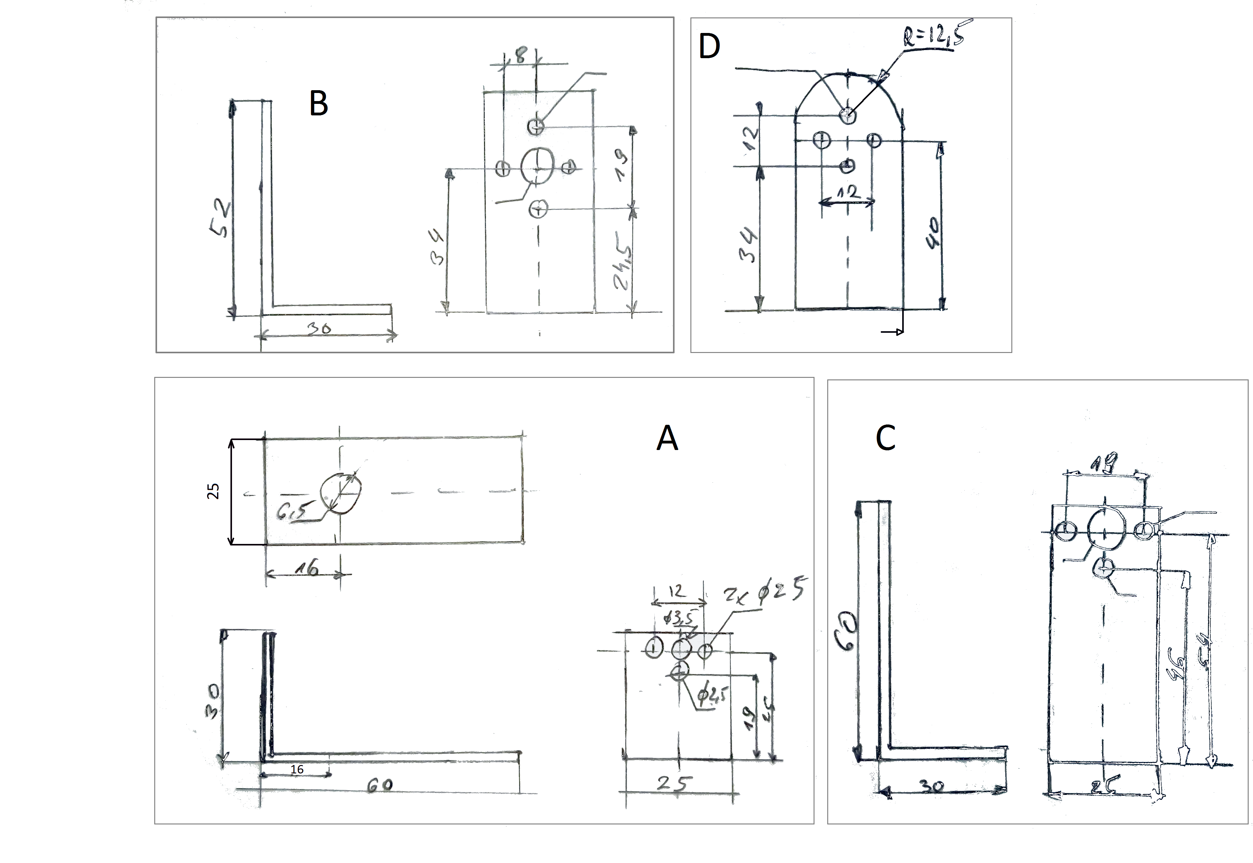
After attacking my action camera with calipers I had rough dimensions and an idea how to connect it to the motors. From an aluminum rectangular tube I had at hand (30x60mm, 2mm wall) I cut two 25mm wide section and cutting at two diagonal corners created four L-shaped parts.
Assembles as shown in picture, dimensions (in mm) shown on hand drawn mechanical sketch.
Gimbal control board has PWM inputs to change pitch and roll and QGroundControl allows to configure AUX1 and AUX2 PWM outputs so they pass position from VRA, VRB knobs on radio transmitter. This allows to move camera while in flight.
What I did to control gimbal by VrA and VrB potentiometers (front corners of the radio):
- In radio controller setup/Functions/Aux. channels assign VrA to Ch7 and VrB to Ch9,
- QGroundControl in Radio section set option AUX1 Passthrough RC channel to CH7 and AUX2 Passthrough RC channel to CH9.
- The Pass-through is active on PWM outputs of fmuk66 PWM_CH5 and PWM_CH6 ONLYafter ARMING !
- You will see PWM_CH5 and PWM_CH6 changing according to Vra VrB potentiometers.
- I had a simple gimbal control board connected to PWM_CH5 and PWM_CH6 and could move gimbal in the air: https://youtu.be/NjekhPAjUK4?t=177The same procedure shall work for other controls/channels from radio as you require.
Whole contraption is a bit heavy, making balancing drone harder. Even shifting battery all the way to the back makes it pitch down. (rear props will compensate it, though I noticed drone being slower to turn, ascend and accelerate. Battery lasts also shorter.
I noticed that drone with camera and gimbal is much heavier and slower to react on commands from RC. After looking at logs it seems it uses most of the time 100% thrust on front motors.
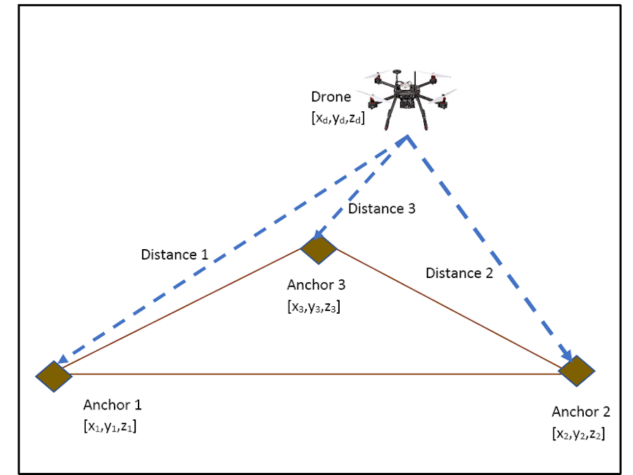
Adding UWB ranging device to PX4 Firmware.My goal for HoverGames was to add UWB ranging device from NXP called Ranger4. It is SPI connected device measuring Time of Flight between second device of the same type. In nutshell it measures time, which is required by radio waves to travel between devices.
The initial idea was to have thee Ranger4 devices, (usually called anchors) on the ground in known locations, for example at three vertices of the triangle. Flying drone above area covered by triangle it should be possible to triangulate position of the Drone. Distance measurements using UWB can reach +- 5cm accuracy and in open field reach some tenths of meters (maybe 50m). Such systems perhaps could allow to fly Drone in case where GPS signal is not available, still having accurate position for autonomous operations.
Currently I have implemented a Ranger 4 class, added new example to nsh.
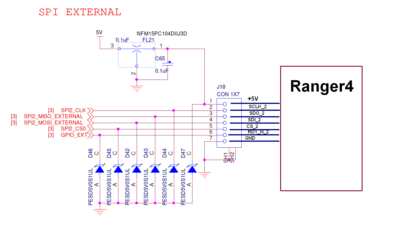
Due to specific timing requirements of Ranger 4, standard spi available in PX4 implementation is not well suited. Ranger 4 seems to require a delay between asserting CS and first clock ~16us. Processor used (MK66FN2M0VLQ18) has hardware support for such delay but so far I did not manage to set it correctly in spi drivers :(
After implementing rough communication with Ranger 4 on bare-metal system I ported it to PX4 firmware, implementing nsh commad uwb start | stop | status.
Due to Ranger4 requirements in SPI communication to test RDY_N line after asserting CS it turned out, that current implementation of NuttX SPI drivers for Kinetis family is not well suited for the task.
By configuring GPIO_EXT as generic GPIO input (instead of CS_1) I managed to sense RDY_N line of Ranger 4. I tested Following approach:
- Manually assert SPI2_CS0 line PORT_LEVEL(GPIO_SPI2_CS, PIN_LOW);
- Wait until RDY_N goes low: PORT_READ_LEVEL(GPIO_SPI2_EXT_AS_RDY);
- Perform SPI transmfer using SPI::transfer() method
- De-asseert SPI2_CS0 line.
To my disappointment I wasn’t able to communicate in correct way with Ranger4. Internal Kinetis implementation of transfer method controls SPI_CS lines, initially de-asserting all available CS lines of SPI port, followed by asserting CS line of selected device, followed by generating clock and data.
The fact that CS line is manually asserted, then reset by spi driver to be asserted again causes communication failures with Ranger4.
After measurements it turns out that RDY_N line is brought to low ( indicating R4 ready to receive data) approximately 16us after asserting CS meaning that SPI clock must appear not earlier than 16us after CS going low. Using plain SPI driver as implemented in NuttX result in clock applied immediately after asserting CS.
Kinetis uC MK66FN2M0VLQ18 used in Drone has hardware support for delaying clock in relation to CS but not yet supported by NuttX driver. Quick test to modify “Clock and Transfer Attributes Register” (SPI2_CTAR0) did for introducing required delay failed.
Despite being able to work with Ranger4 on bare-metal system (based on S32K144) I was unable to achieve range measurements on PX4 platform.
Planned solution to overcome SPI limitation is to use additional microcontroller to connect with Ranger4 that fully support RDY_N, INT_N, nRST requirements and use auxiliary UARTS of PX4 platform to provide results to Drone.
After achieving this task estimating drone location based on triangulating location and publishing it over MAVLINK shall be implemented.


Comments
Please log in or sign up to comment.