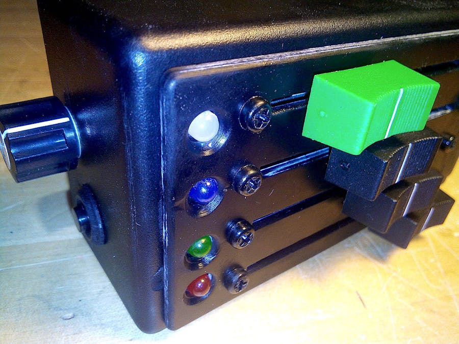
In these days a complete and rich lights control DMX console is available to buy at shops for a few tens of Eur only, but we also know how is interesting and exciting to build one by ourself. Here it is mine, a basic complete circuit to control RGB (red, green and blue) lamps by the way of sliders, in a small handy box. You may also control brightness of all combinations of colours. A push button toggles RGB and STROBO mode, and with the rotary potentiometer you may change the strobo frequency rate. Coloured LEDs are just to remember the single functionality of the sliders, always on. The transparent LED is a multicolour RGB one: it varies his colour following the corresponding RGB sliders and it flashes at 4Hz if the strobo mode is active. Power up the circuit by the way of an USB cable. Connect this circuit to one or more DMX capable RGB lamp using a XLR 3 wires cable (the one used for microphones); put a 120 Ohm terminator to the last lamp.
Schematic Diagram (Fritzing):- Arduino Nano MCU
- C25B TTL/RS485 communication board
- 10k linear rotary potentiometer
- 4 x 10k linear slider potentiometers
- 100nF capacitor
- Push button normally open
- Red 5mm LED
- Green 5mm LED
- Blue 5mm LED
- RGB 5mm LED
- Resistors: 10k, 2 x 680, 120, 2 x 470, 270
- 25 copper rivets (for PCB pass through holes)
- 3 pins strip line for XLR connector
- DMX (XLR) 3 pin female panel connector
- USB-B female PCB connector
- 4 x huts for the sliders
- 1 x hut for the potentiomenter
- 1 x hut for the push button
- Plastic black box 129x64x45 mm
- USB cable for power
- Cover, Ring and Mounting supports (see NOTES below to download 3D models)
- Optionals: DMX/XLR 3 wires cable and connectors male+female, 120 Ohm DMX/XLR terminator, one or more RGB lamps with DMX capabilities
The circuit I am showing here uses 5 DMX channels: ch.1 for brightness, ch.2 for red, ch.3 for green, ch.4 for blue; for each channel their values 0-255 changes brightness or colours according. Channel 5 is used for Strobo mode: in this case the values 0-7 do nothing, the values 8-255 changes the strobo rate. You have to set the lamp with code 001 as first channel number (look at your lamp user manual to set it).
Please read at this link to better understand DMX communication protocol: https://www.theatreartlife.com/staying-still/dmx-demystified/
To test the circuit you may connect the Arduino D3 (3) pin, used as TX, to an oscilloscope and see a signal like the picture above. After that you may do the same connecting the oscilloscope after RS485 board to view two similar signals, one on pin A and the other on pin B, but with different voltage level and A inverted vs. B, as per 485 protocol characteristic. The communication signal is transmitted continuously regardless you are playing on sliders and buttons or not.
The C25B RS485 board already got the 120 Ohm terminator permanently connected as "BEGINNING" of the DMX cable. You have to terminate also the "END" of the cable, or chain of cables, at the last connected lamp if you have more than one, with a dedicated terminating connector with a simple 120 Ohm resistor inside between pins 2 and 3 of the cable. A correct termination is important to be sure the RS485 specifications are respected and everything will work strongly well.
#include <DmxSimple.h> The program uses DmxSimple library
#define IS_DEBUG false Change from false to true if you like to see Serial monitor showing you what happen when you are playing with controls
const byte TTL485Pin = 3; This and other lines to declare all input and output Arduino pins used in this project
void setup() This block of code to initialize library and in/out pins
void loop() Main block code: reads button, trimmer and sliders, and according with refreshRate (set to 200m/sec) transmits information about RGB colours and strobo to the lamp/s by the way of RS485 module and XLR cable.
void blinkLed() Used to blink at 4Hz (four times per second) RGB led when strobo mode is active
void readButtons() Reads digitally if the RGB/Strobo button is pressed and sends information to the lamp/s
void readTrimmers() Reads analogically the actual position of the trimmer and the four sliders; it also "maps" the values from 0-1023 to 0-255 (from 10bits to 8bits)
void writeDMX(const byte ch, const byte val) It sends values to the lamp/s using DmxSimple library
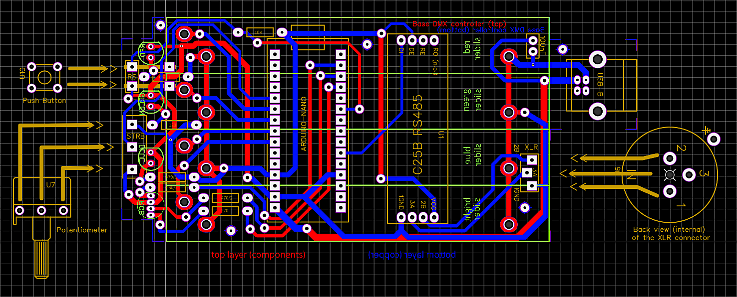
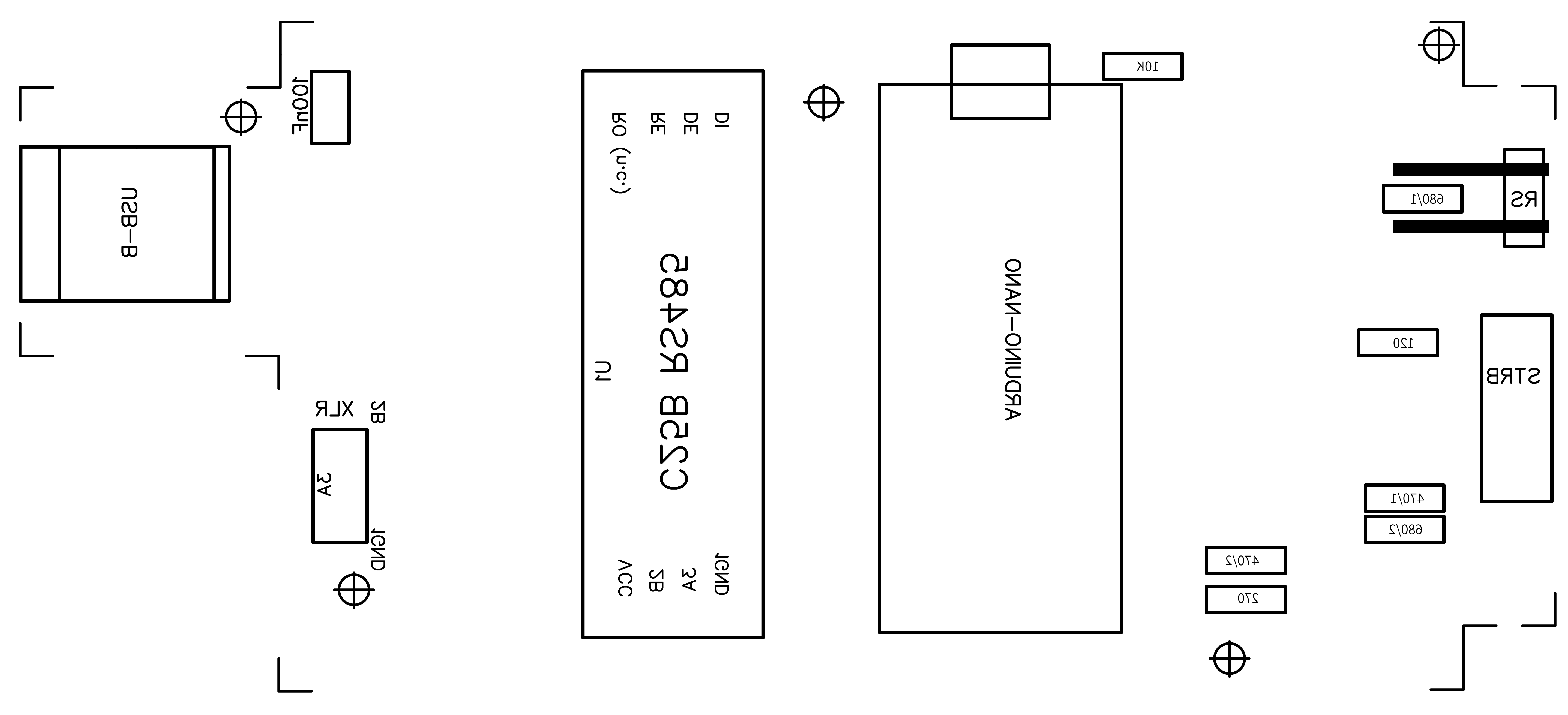
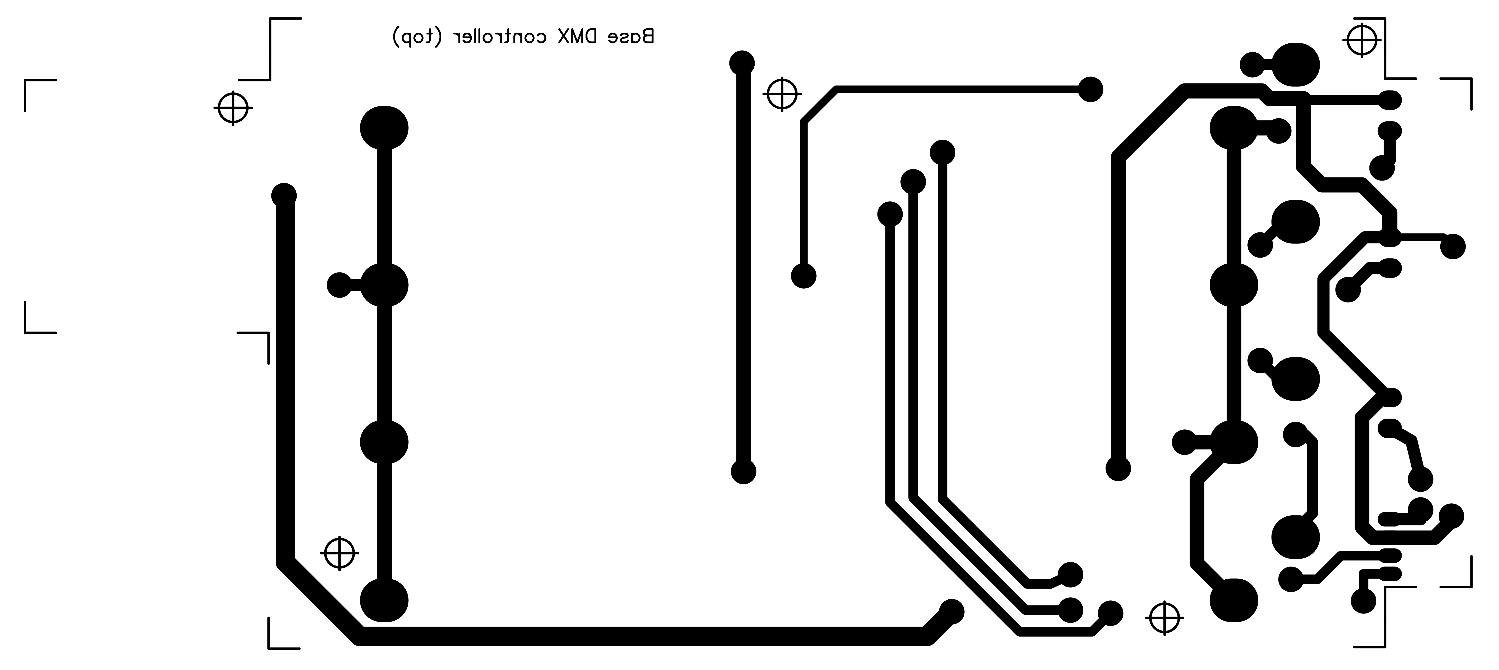
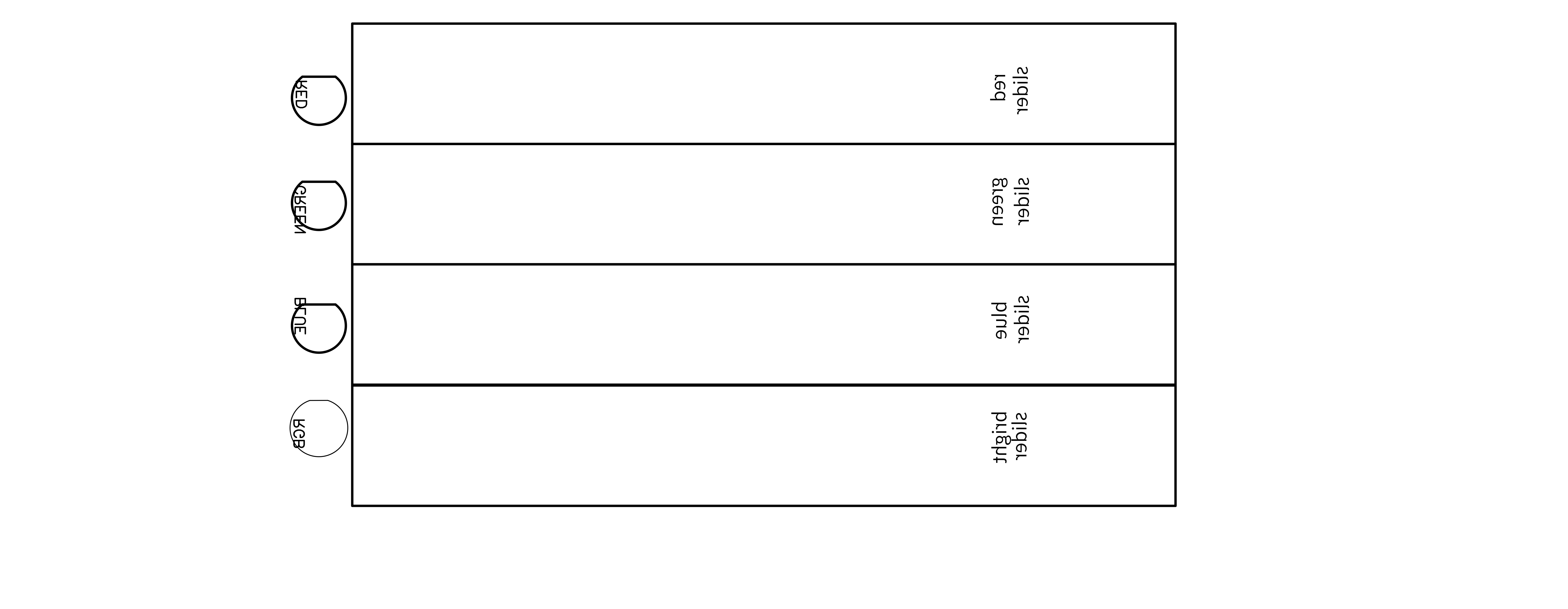
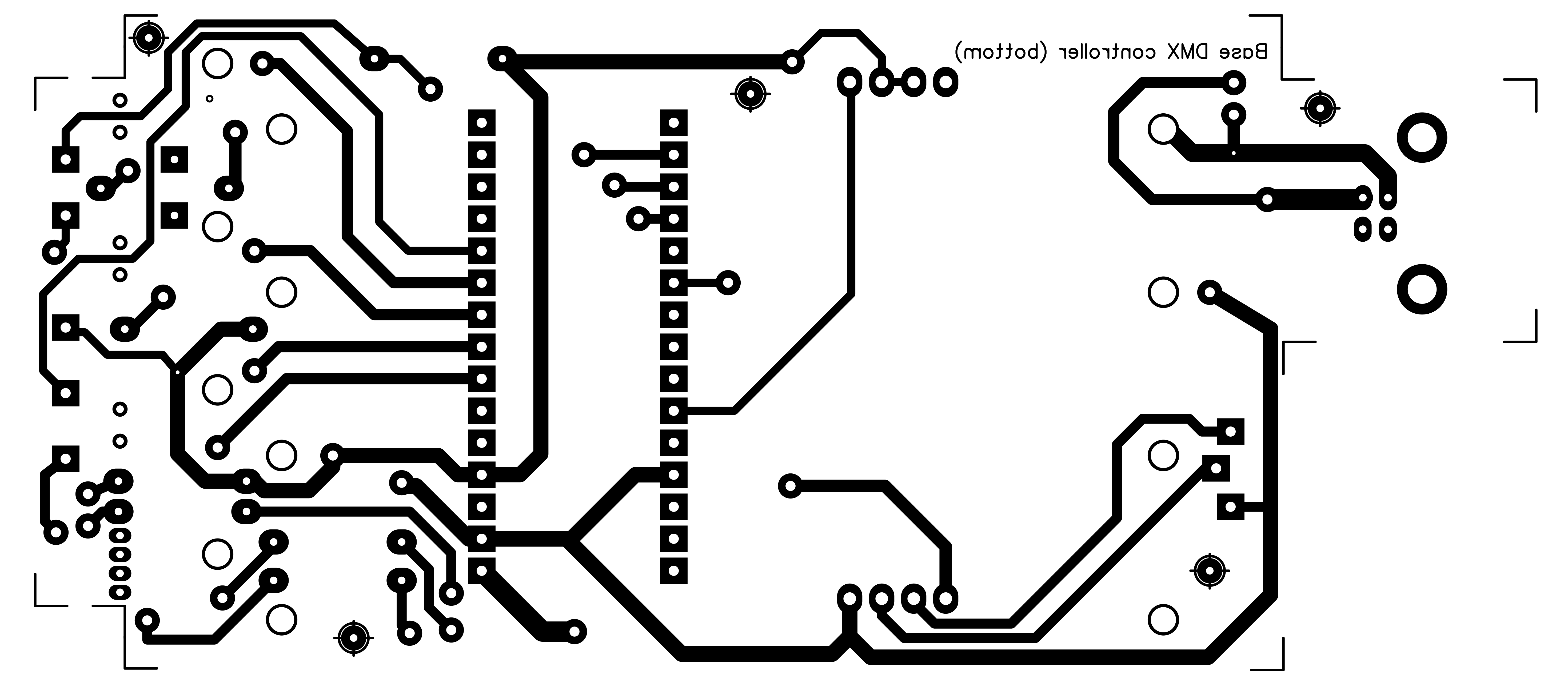
PCB (printed circuit boards):I used a double faced PCB for that reason approx. 25 pass through rivets or pins are used to solve routes for whole circuit. There are also 5 alignment spots holes to make at first. I designed on every PCB face these 5 alignment spots. In download section you have all PCB files, components and solder faces, mirrored, for downloading and printing by the way of a laser printer on "yellow" or "blue" sheets; I used the blue ones but also the yellow ones are good and the price is lower. I have to say the blue sheets are better... When printing remember to disable toner saving settings, use instead 1200 dpi resolution to have deep real black result. The toner transfer process from magic sheets to PCB is made by the use of an hot iron... Around in the Net there are some tutorials showing how to produce a good PCB but remember these important points: clean perfectly and slightly brush the copper with a kitchen ruvid sponge, 5 minutes of ironing, cold water thermal shock, two faces alignment by the way of 5 holes (I used 5 pins on a large white LED surface to see holes), protect with transparent adhesiv tape the other face during corrosion process. Printing also components designs makes the project "professional" and more simple to place them correctly :-)
After the PCB board is made, first of all place and solder the rivets both faces, then is the time of all top components face; the last is the bottom components: 4 sliders and 4 LEDs. Connect also external components, potentiometer, the push button and the XLR connector to the correct pin number 1, 2 and 3. I installed the small push button vertically with two pins soldered on the PCB, the other 2 pins are connected to other two solder spots just to keep it in place more strongly when pressing it.
Usually I make the plastic box by myself projecting and printing it with a 3D printer but this time the box is larger then my printer capabilities, so I had to buy one. To put everything inside this plastic box is tricky. If you are a Tetris good player it can be helpful! I lets you playing around... let me know :-D
-----------------------------------
NOTES & Improvements:- 13.03.2021 : to complete the project I prepared three 3D .STL models at this link https://grabcad.com/library/components-for-dmx-rgb-box-1 where you may download files regarding: a cover panel to place under the sliders and surrounding LEDs, a 18mm tube mounting support (it needs 4 of them) and a ring to put around the push button.
Enjoy with lights and music!





Comments
Please log in or sign up to comment.