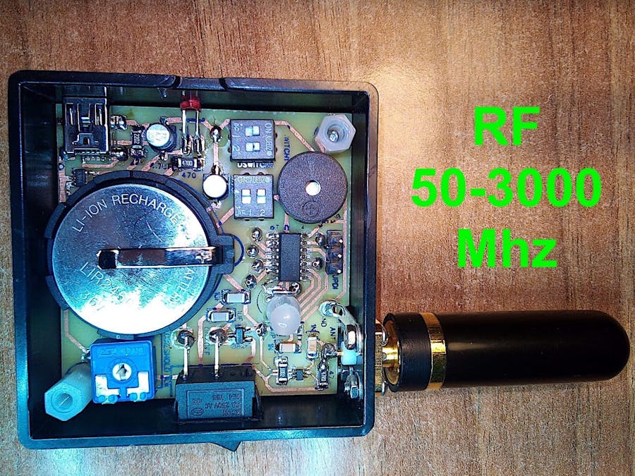
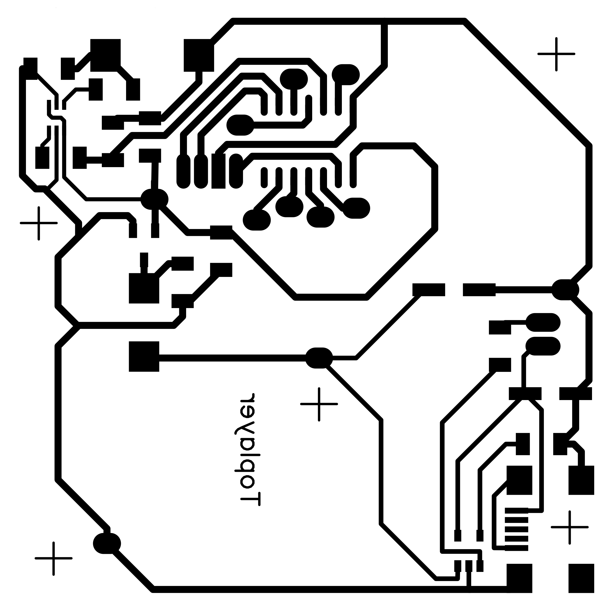
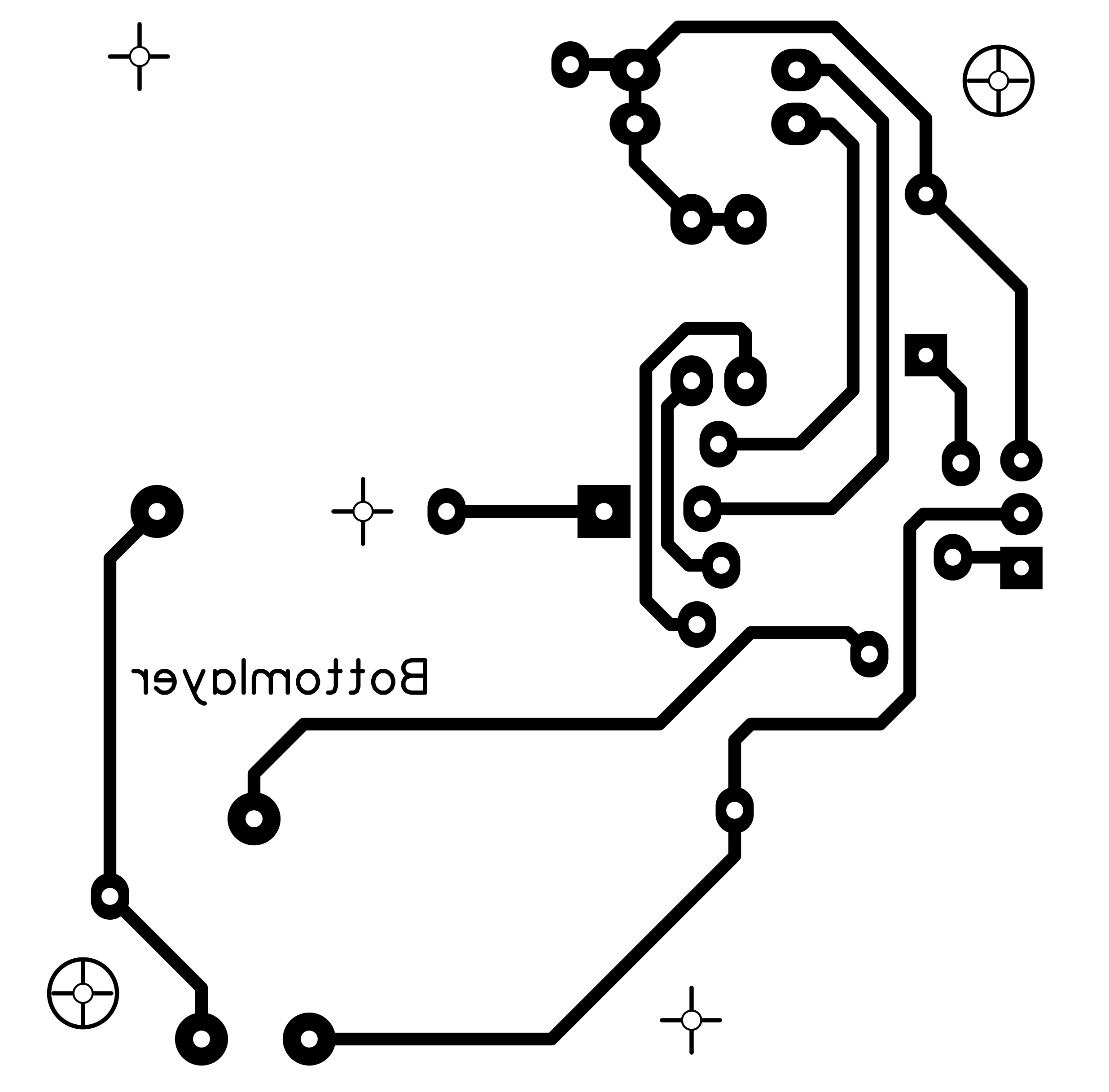
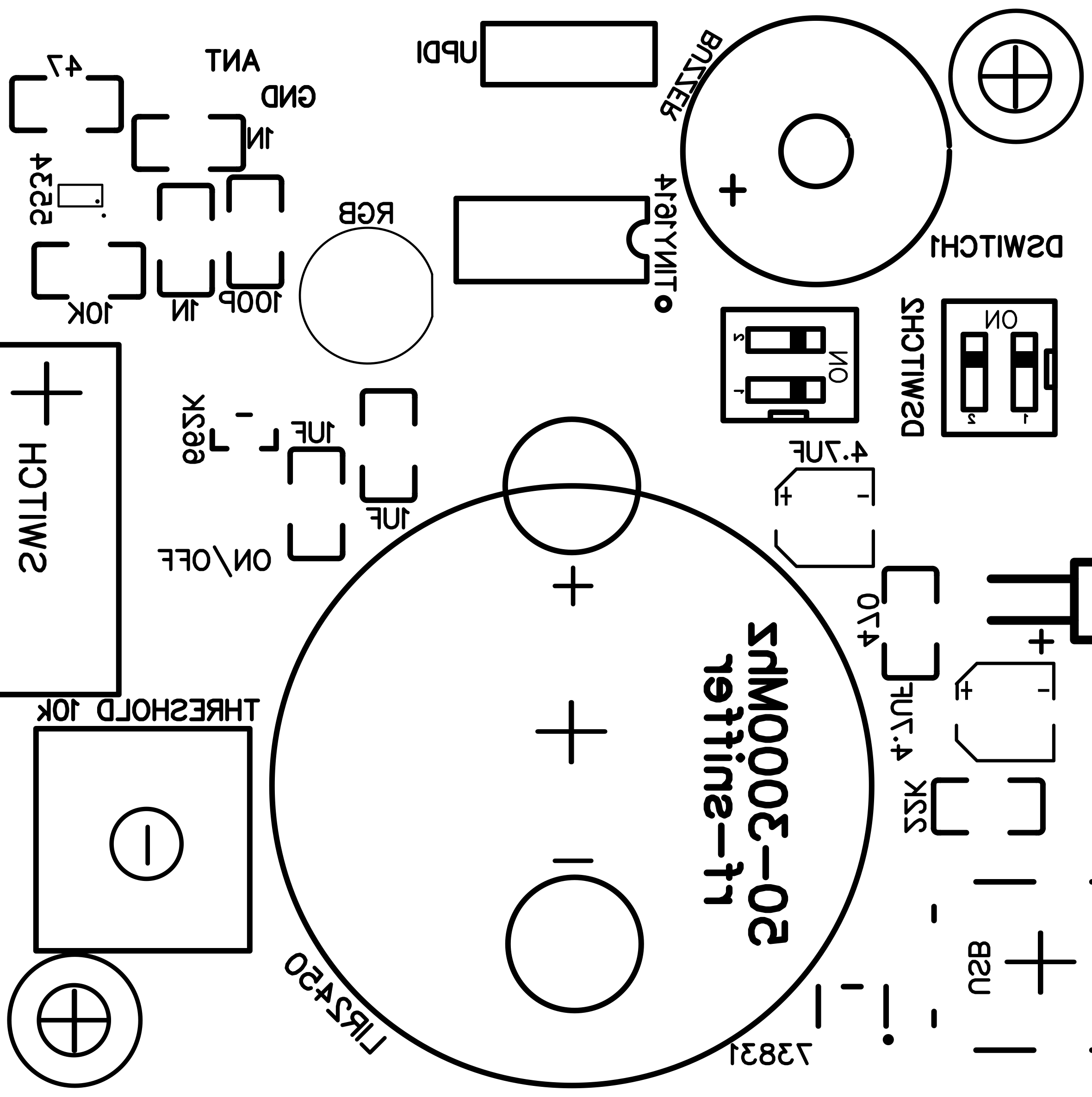
The RF detector can be used as linear instrument monitor or as threshold/comparator alarm. DipSwitch1-1 setting: On=buzzer on, Off=buzzer off. DipSwitch1-2 setting: On=instrument, Off=comparator. The threshold level comes from 10K trimmer you may set as you like. In comparator/alarm mode the top panel RGB led and the buzzer will flash/beep 3 times when RF signal is greater then trimmer position; additionally, every 10" a single flash of green color led will let you know the comparator is on and working. In instrument mode both buzzer and top panel RGB LED change their level (sound & light) depending of the detected RF power level.
By the way of DipSwitch2-1 and DipSwitch2-2 you may change the colour of the top panel RGB LED: 00=off 01=red 10=green 11=blue.
It is an USB mini connector to recharge the battery from an USB power source, and a small red colour LED, on the side, to show when it is charging.
Inspired from John Bradnam's ATtiny 1614 Project I bought a couple of this microcontrollers to take a new way and enjoy a new adventure, I made MyTiny first testing circuit. Everything is working on my choice to power it at 3.3v. Up to today I tested and verified: digitalRead, digitalWrite, analogRead, analogWrite both PWM and DAC; I provided a serial monitor through pins RX/TX <-> FTDI serial interface and SoftwareSerial library; finally I connected an OLED 128x32 display by the way of SDA/SCL and Wire library. Cool!
ATtiny programming:To program the ATtiny by the way of an Arduino NANO and IDE please read Bradnam's instructions at above link. Here some of it:
- install jtag2updi sketch into Nano
- connect a 10uF 25V electrolytic capacitor on Nano between RST (+) and GND (-)
- connect a 4.7K resistor and a wire from Nano pin D6 to ATTINY pin UPDI (pin 10)
- connect GND pin from Nano to ATTINY GND (pin 14)
- connect +3.3V pin from Nano to ATTINY VCC (pin 1)
- keep connected Nano and Arduino IDE
- on IDE change programmer to "jtag2updi"
- on IDE change board to "ATtiny1614..."
- on IDE change other parameters as per attiny-setup.jpg screenshot (see below)
- on IDE compile the sketch to install on ATTINY
- on IDE Upload the sketch to ATTINY (by the way of Nano still connected)
- the ATTINY should run with the installed sketch
- you may disconnect ATTINY from Nano...
- LT5534 50-3000Mhz RF power detector IC
- ATtiny 1614 3.3V MCU
- LIR2450 3.6V rechargeable battery + PCB holder
- MCP73831 Li.Po. controller charger IC
- Active buzzer
- 2x two dipswitch
- 10k trimmer
- RGB 4 pins led
- Red led
- SMA-M (144-430Mhz small antenna)
- SMA-F panel connector, square + screws
- On/off switch
- 2x SMD 4.7uF capacitors
- 2x SMD 1nF capacitors
- 2x SMD 1.0uF capacitors
- SMD 10k resistor
- SMD 22k resistor
- SMD 47 resistor
- SMD 100pF capacitor
- SMD 470 resistor
- SMD SOT-23 662K 3.3V voltage regulator IC
- 3 pins connector for UPDI (1=UPDI, 2=3.3V, 3=GND)
- SMD USB-mini connector
- Plastic or metal box 51x51mm internal size
- 9x copper pass through rivets
- Capacitors and resistors SMD size is C1206;
- Components are small, and 5534 RF detector IC is VERY SMALL! To solder it I had to use an electronic magnifier!
- The 22kohm is the charging current resistor. The formula is: 1000/22000=0.045A (45mA). In the typical application schematic diagram shown above the resistor is a 2kohm, it means the charging current will be 1000/2000=0.5A, too much for this small coin battery. I had to modify it of course;
- Remember to connect a specific antenna for every RF frequency range you want to detect; in some cases a simple ring wire of any length can be enough as "antenna", specially when the RF signal is strong;
- LT5534 datasheet says to not overload the RF input pin with signals > 10dBm it means you should stay below 0.01W near the IC (i.e. transmitting with an handheld 5W radio near the IC is dangerous); if it is the case, I suggest to put an attenuator between the antenna and the box (i.e. 20dBm or more, SMA-MF serial external attenuator, see the picture below); together with the attenuator, use full metal box or cover the interiors of the plastic box with copper foil, or paint/spray and cook at 80°C if necessary (read material datasheet) with conductive graphite material the interiors of the box, to avoid RF signals passing through the box; I chosen the copper foil way with a wire connecting the main box and the cover, all to the ground. The RF signals should pass through antenna only... Burning the IC with too much RF power is a real possibility: I did it one time.
- 24.05.2023 - testing the attenuator mentioned above (see the picture below) I can say it doesn't do the work, even more I can say it is "dangerous" because let pass more RF though it; probably its shield is bad. I suggest to not use this model! If you have tested something good please let me know.
- 17.09.2023 - more about attenuator (from Bard A.I. by Google): "Yes, it is possible that the received signal level is higher with an attenuator between the antenna and the circuit in an RF sniffer. This can happen if the attenuator is not properly matched to the impedance of the antenna or the circuit. When an attenuator is not properly matched, it can reflect some of the signal back to the antenna. This reflected signal can then be amplified by the antenna and added to the incoming signal. This can result in a higher overall signal level at the input to the circuit."
- 20.04.2025 - RGB LED: after a while (two years :-) ) I discovered the RGB mentioned LED is without a limiting current resistor, I forgot to put one in the project. Even I did not have any problems till now using it as is, I suggest to install a 220 Ohm resistor between GND LED pin and the GND; cutting the track, on the top layer, at the left of the UPDI connector should be a good place to put the resistor in between.
Enjoy it!
Marco Zonca


Comments
Please log in or sign up to comment.