So a few years back, I was doing some cleanup in my basement and I found a storage box full of electronic items (stuff that I paid 10c for a pack of capacitors somewhere in 1988!) when I was in college … I was ready to give everything away when a colleague at work (funny part, he too has an electronic background and is very involved in electronic projects, especially with 3D printing – see his channel Science3D) showed me how tinkering was done today using either an ESP8266 or Raspberry Pi. Must of all, how easy it was to connect the ESP8266 to a computer using an Arduino IDE or Visual Studio Code!!
After poking the internet for sites like Hackster.io; hackaday.com; instructables.com, etc. I decide it was time for me to give back to the community and share my projects…
I’ve done a project to open my garage door using a web interface and a keypad with the help of a Raspberry Pi v3. It’s been 2 years now and honestly I haven’t used the keypad simply because the web interface is much more practical (especially for my kids). So I decided to remake the garage door opener (using a dedicate controller - Wemos D1 mini) and it will be installed at my sister-in-law that always forgets to close her garage door… Therefore, this will be my first post!
PoC (Proof of Concept)
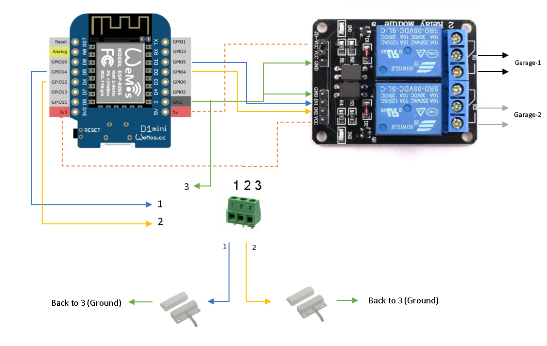
First, validate your project on a breadboard. I’ve used some Jumper Wires to simulate the magnetic contact switch and testing the open or close state of the garage door.D5 and D6 are set as ‘INPUT’ Pins (enable internal pullup). For example, if your garage is open and the magnetic contact switch are in perimeter next to each other, the assigned pin (D5 for example) will read ‘0’ and that will be the open ‘state’.
RELAY
D1 and D2 are set as ‘Output’ Pins. Just remember, to activate the relay (IN1 for example) we will need to output a ‘0’ on pin D1 (GPIO-5) from the ESP8266. This will sink the current from VCC (3.3v) on the relay board to D1 and activate relay. Make sure to remove the jumper that connects JD-VCC & VCC. Add 5v from the ESP8266 to JD-VCC and 3.3v to VCC (see schematic). I added a link that explain in details the functionality of this relay YoutubeRelay.
When the GPIO’s are assigned and the code is working properly, we are ready to finalize the project. I always try to have a good finishing product. So, I used my 3D printer to obtain a base layer that will hold my components in place without having to solder on a perf board. I used hot glue to hold the components firmly on the 3D printed layer.Don`t forget to add the jumper wires.
VERY IMPORTANT - On the relay board, remove the jumper between the JD-VCC and VCC.
Find a good location for the ESP8266 board (close to a power outlet). Pass the wires (I use a 4 conductor wire for alarm) from the magnetic contact switch to the ESP8266 board (green terminal) and wires from the relay (NO & COM) to the garage controller.
Find a good location that will hold the magnetic contact switch. I printed a piece that will be added on the garage railing and use hot glue to hold it in place. The wires will go back to the ESP8266 board (see schematic)
Connect 2 pieces of wire from the relay (com1 & no1 for the garage-1) or (com2 & no2 for garage-2) to the back of the garage door controller (see picture). Look into your manual or follow the wires from the push button from the wall...
Open a browser with the IP address of the ESP8266. In manual mode, the garage will stay in whatever state it is without been closed by the ESP8266.
UPDATE (2024-01) - I made some modifications a few months ago...
To begin, I purchased a new contact switch with strong magnetic contact and can be mounted flush on the wall. Make sure the magnetic contact is NC (normally closed) when the garage door is NOT open.
I'm now using Blynk application to remotely open/close the garage and receive state information.
The 3D base is also updated and the ESP8266 is now horizontally.


Comments
Please log in or sign up to comment.