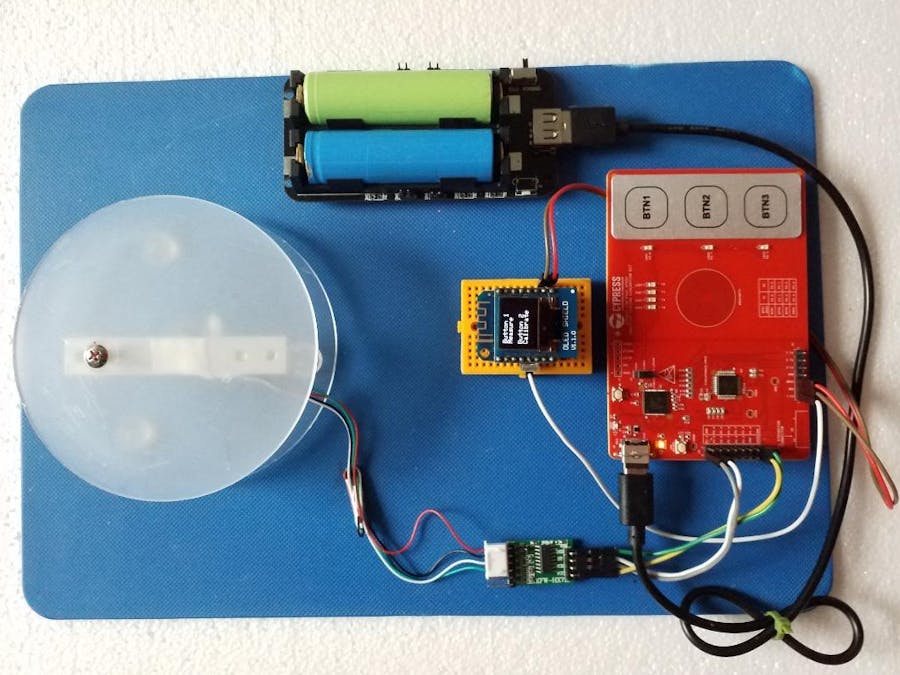
Several requests from our clients, primarily in the agricultural and manufacturing sectors, led us to take on this project.
In our previous prototype, we used three mechanical push buttons.
1) On/Off
2) Calibration
3) Log
Some drawbacks we faced when using mechanical push buttons;
1) Easily damaged
2) Not waterproof
The reasons to replace push buttons with inductive sensing buttons are as follows;
1) Robustness
2) Waterproof
3) Industrial grade
4) Dustproof
5) Reduce maintenance costs
6) Precision
7) Ergonomic
Operations
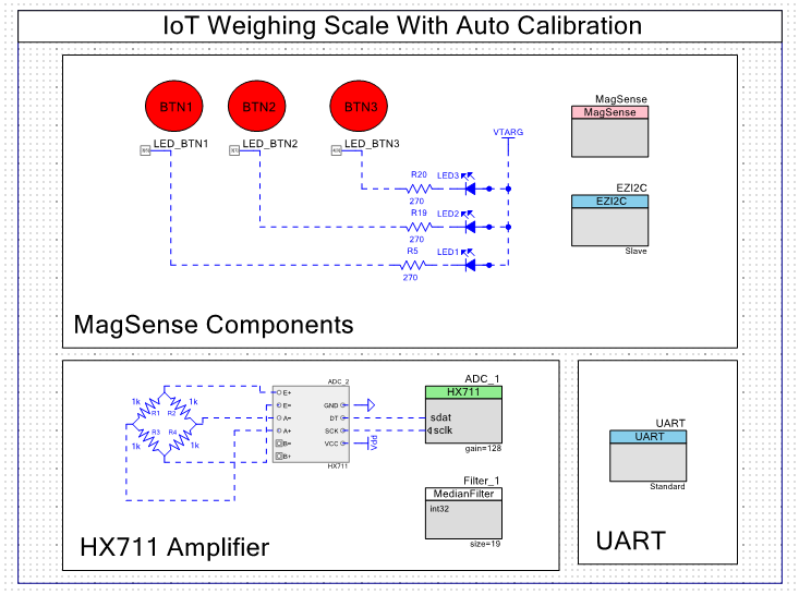
We used 2 touch buttons;
1) Button 1 (BTN1) - Measure and Log.
2) Button 2 (BTN2) - Calibration.
Calibration is done by pressing BTN2 and adding a 1.5kg weight plate to the load. Off Load ADC value and With Load ADC value were measured to calculate the calibration factor
Pressing BTN 1 will measure any loads added to the scale and store the data in the cloud The data are also displayed on OLED and mobile apps. For this project, we utilized Blynk Cloud and the Blynk Mobile App.
Demo
HX711 Functional Description
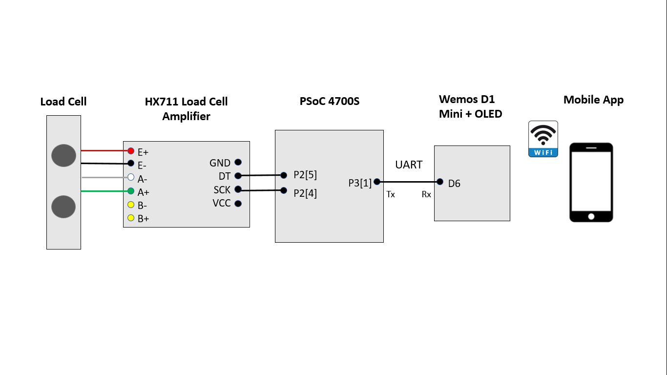
The HX711 is a precision 24-bit analog-to-digital converter (ADC) designed for weighing scales and industrial control applications to interface directly with a bridge sensor. It has ADC, oscillator, bandgap reference, and power supply regulator integrated into the single chip.
HX711 Parameters and Settings
For this demo, we used a 10kg rated load cell attached to the HX711.
ADC_gain (128 / 64 / 32)
The input multiplexer selects either Channel A or B differential input to the low-noise programmable gain amplifier (PGA). Channel A can be programmed with a gain of 128 or 64, corresponding to a full-scale differential input voltage of ±20mV or ±40mV respectively, when a 5V supply is connected to AVDD analog power supply pin. Channel B has a fixed gain of 32.
The HX711 has three available ADC input scales: ±20 mV, ±40 mV, and ±80 mV. The ADC samples input A when ADC gain is set to 64 or 128. When the ADC gain is 32, the ADC samples input B.
For this demo we set ADC gain to 128.
state_check (polling/interrupt)
Selects how the ADC data ready status is detected. Valid options are polling/interrupt. When interrupt option is selected, an external interrupt on irq pin should be configured by the user. When polling option is selected, the irq output pin becomes hidden. By default, the component is configured for polling.
Here we used the polling method.


Comments
Please log in or sign up to comment.