The power monitor takes an important role in smart home devices. There are many power monitors available on the market. The most of such monitors have only one function - they display the total consumed energy on the LCD.
Today power monitors can be smart. The modern smart power monitor can measure power, current, voltage, AC frequency and leakage current.
Such monitor also checks the measured values and checks for the overcurrent and the overvoltage. Based on the required limits, it can switch on/off the consumed devices in the smart home from the main line (220 V).
There are power monitors with the Wi-Fi support. Such devices can send data to the user's mobile device. Also, the user can control the power monitor's parameters, such as the overvoltage and overcurrent limits.
In general, power monitors can be for the DC and AC power supply.
Smart Power Monitor with Matter StandardThe proposed project is the Smart power monitor with Matter standard for the DC power supply. It can be used as a standalone device or as a part of another Matter device. Also, it can be easily redesigned to measure the AC power.
The Smart power monitor consists of such blocks: nRF7002 DK, the LCD HD44780 shield, the relay module, current and voltage sensors.
The power monitor continuously measures the DC current and the DC voltage. Based on these values, it calculates the power and the total consumed energy.
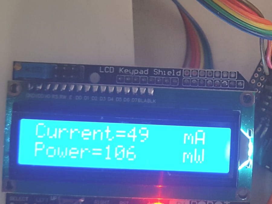
The current and the power are displayed on LCD. Also, the current, the voltage, the power and the total consumed energy are sent to the CHIP tool application through the Matter protocol. The Chip tool is the default implementation of the Matter controller role. See here for the details.
The user can use the CHIP tool to set the minimum and maximum values for the current and voltage. The device switches off the load in case when the current and voltage exceed the these limits. Additionally, the user can forcibly switch on or switch off the load.
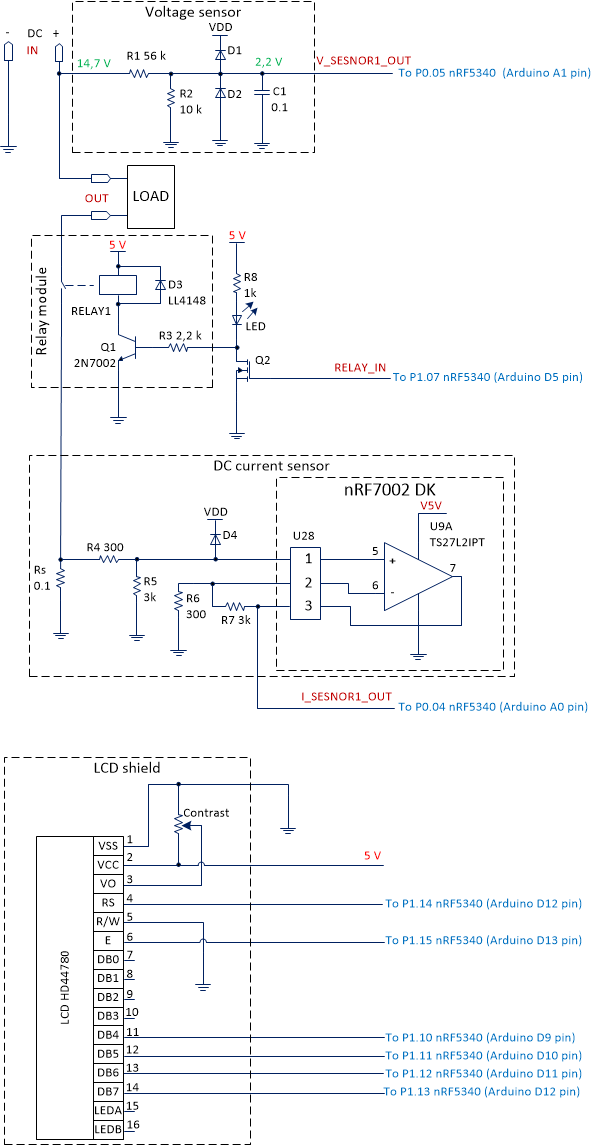
Hardware DescriptionThe hardware consists of sensors, the relay and the LCD module connected to nRF7002 DK. The electrical schematic is shown below.
The next picture shows the photo of the connections to nRF7002 DK.
The voltage and current sensors connect to the power line of the load. Their outputs connect to nRF7002 DK. nRF7002 DK controls the relay module, which switches on/off the load. Let's describe each module in detail.
The Voltage SensorThe voltage sensor schematic is shown below.
The sensor measures the voltage on the load. In our case, the load supply voltage is 14.7 V. So, the sensor has the resistor divider R1, R2 to reduce the voltage for the acceptable ADC range. The ratio of the divider is 6.7.
You can set your own values of R1, R2 if you have the load with the different power supply. Use the formula to calculate these values:
Uout = Uin * R2/(R1 + R2)
The diodes D1 and D2 protect the nRF5340's ADC from the high input voltage. The capacitor C1 filters the input voltage.
The voltage sensor output connects to pin p0.05 of nRF5340 (or A1 pin on the Arduino header of the nRF7002 DK board).
The Current SensorThe current sensor measures the consumed current of the load. The current sensor schematic is shown below.
The classic low side current sensing circuit is used here. It consists of the sense resistor Rs and the differential operation amplifier (OP) U9A.
The resistors R4, R5, R6 and R7 define the gain of the amplifier. The gain is determined by the ratio of R2 to R1. In our case, it is 10. The diode D4 is optional, and it takes the rode of the high voltage protection.
The resistor Rs must be precise and it has a small resistance. Also, R4, R5, R6 and R7 must be precise too. Otherwise, you have an additional error due to the high common mode voltage. The current sensor in such configuration can measure currents up to 3.6 A. The range can be changed by Rs and the gain of OP.
To measure currents up to 100 A I recommend using the Hall effect current sensor, for example the Winson WCS1700. In this case, you can use OP U9A as a repeater.
Note, I used the unused operation amplifier U9A on the nRF7002 DK. This extra op-amp is routed to the not mounted connector P28. I have soldered the connector P28 to the nRF7002 DK. After that, I soldered a simple schematic of the resistors R4-R4 above the connector.
The relay module is optional and can be used to switch on/off the load. I used the standard relay module board, which consist of the relay with the control transistor. Unfortunately, the nRF5340 GPIOs have levels 1.8 V which are not enough to switch the relay module directly. I used the additional MOSFET to control the relay module.
I used the HD44780 based LCD shield for Arduino. Unfortunately, the LCD shield has pins which conflict with buttons and LEDs on nRF7002 DK (P1.06 - P1.09 of nRF5340 or D4 - D7 Arduino pins of nRF7002 DK). I used the wires to connect the LCD to P1.10 - P1.15 pins of nRF5340 (or D8 - D13 Arduino pins of nRF7002 DK).
The firmware was developed based on the Template example, which already has minimal implementation of the Matter application layer. This example also has the implementation for Button 1 and LED 1 (available on nRF7002 DK), which are used for the factory reset procedure and commissioning an application.
To implement the ADC and HD44780 LCD, I used existing code examples which are available in Nordic Semiconductor nRF Connect SDK.
The project consist of the following files:
- main.cpp - the main file where the application starts
- app_task.cpp - the file which contains the main routines
- app_adc.cpp - the file with functions for ADC
- app_hd44780.cpp - the file with functions for LCD
- zcl_callbacks.cpp - the file with callbacks for the Matter communication
- headers
Also, the file prj.conf additionally contains CONFIG_ADC=y to enable ADC. The file nrf7002dk_nrf5340_cpuapp.overlay must contain the configurations for two ADC channels:
/ {
    zephyr,user {
        io-channels = <&adc 0>, <&adc 1>;
    };
};

&adc {
    #address-cells = <1>;
    #size-cells = <0>;

    channel@0 {
        reg = <0>;
        zephyr,gain = "ADC_GAIN_1_6";
        zephyr,reference = "ADC_REF_INTERNAL";
        zephyr,acquisition-time = <ADC_ACQ_TIME_DEFAULT>;
        zephyr,input-positive = <NRF_SAADC_AIN0>; /* P0.04 */
        zephyr,resolution = <12>;
    };

    channel@1 {
        reg = <1>;
        zephyr,gain = "ADC_GAIN_1_6";
        zephyr,reference = "ADC_REF_INTERNAL";
        zephyr,acquisition-time = <ADC_ACQ_TIME_DEFAULT>;
        zephyr,input-positive = <NRF_SAADC_AIN1>; /* P0.05 */
        zephyr,resolution = <12>;
    };
};
The channel adc 0 is used to measure the current (pin P0.4), and the channel adc 1 is used to measure the voltage (pin P0.5). The gain=1/6 and the internal reference provide the input ADC range 3.6 V.
The template.zap file and the zap-generated folder contain the code which represent the Matter device data model. This model has a hierarchical structure and describes the device's features.
The Power Monitor Data ModelThe Power Monitor data model has two endpoints: Endpoint 0 and Endpoint 1. Endpoint 0 is a mandatory endpoint for each Matter device. Endpoint 1 includes the On/Off and Electrical measurement clusters which are specific for the power monitor.
The On/Off cluster is used to control the load. The user can remotely switch on/off the load with a Matter controller.
The Electrical measurement cluster provides the electrical attributes such as dc voltage, dc voltage min, dc voltage max, dc current, dc current min, dc current max, dc power, total active power, etc.
The Power Monitor OperationThe file app_task.cpp contains the event handlers for Button 1, LED 1 and the electrical power calculation. Button 1 and LED 1 play the same role as in the Matter: Template example.
The device calculates the electrical power as the product of voltage and current. It is done in the AppTask::SensorMeasureHandler() function. This function calls the functions AppAdc::GetAdcCurrent() and AppAdc::GetAdcVoltage() to get the measured current and voltage. Then it calculates the electrical power and the total consumed energy. Also, the AppTask::SensorMeasureHandler() function updates the attributes of the ElectricalMeasurement cluster and values on the LCD.
The AppTask::SensorMeasureHandler() function is called every 500 ms on the event SensorMeasure. The APP_ADC_VOTAGE_DIV and APP_ADC_CURRENT_0_DIV constants in the file app_adc.h can be adjusted for better measuring accuracy (or when the sensors are replaced and the input range for ADC is changed). These constants are used to calibrate the device.
The AppTask::SensorMeasureHandler() function checks the current and the voltages for the maximum values: dc-current-max and dc-voltage-max. If the measured values exceed the maximums, the program switches off the load. The dc-current-max and dc-voltage-max values can be set with the Chip tool which can play the Matter controller role.
The user can manually switch on/off the load with the Chip tool. Also, the Chip tool can be used to read measured values. The examples of commands are:
sudo ./Downloads/chip-tool electricalmeasurement read dc-current 1 1
sudo ./Downloads/chip-tool electricalmeasurement read dc-voltage 1 1
sudo ./Downloads/chip-tool electricalmeasurement read dc-power 1 1
sudo ./Downloads/chip-tool electricalmeasurement read total-active-power 1 1
The above commands read the current in mA, the voltage in mV, the power in mW and the total consumed energy in mW*hour.
Quick Start GuideTo use the Power Monitor, you should perform the steps below.
STEP 1. Assemble the hardware accordingly to the attached schematics.
STEP 2. Install the CHIP Tool for Linux or macOS. Details are here: https://docs.nordicsemi.com/bundle/ncs-latest/page/matter/chip_tool_guide.html.
STEP 3. Install Visual Studio Code with the nRF Connect for VS Code extension (with SDK). See nRF Connect SDK Fundamentals lessons for the details.
STEP 4. Unzip the attached pmonitor_dc.zip and open the project in Visual Studio Code. Build it for nRF7002 DK with nrf7002dk_nrf5340_cpuapp.overlay. Flash the nRF7002 DK.
After flashing, the device starts sending voltage, current, power and total energy to PC terminal. Also, it is ready for a commission - LED 2 makes a short flash on (50 ms on/950 ms off).
STEP 5. Do the device commission with the CHIP Tool. The commission is performed similar to the Matter: Template example. Refer to this example for details.
The example of command for the device commission:
sudo ./Downloads/chip-tool pairing ble-wifi 1 Tank 012345678 20202021 3840Note: Tank is the Wi-Fi network SSID and 012345678 is the Wi-Fi network password. The Downloads - the folder with the CHIP Tool application.
See the video with the commission demonstration:
STEP 6. Send Matter commands to read the current in mA, the voltage in mV, the power in mW and the total consumed energy in mW*hour. Also, you can control the load with Matter commands.
Examples:
Read the current value:
sudo ./Downloads/chip-tool electricalmeasurement read dc-current 1 1Read the total energy value:
sudo ./Downloads/chip-tool electricalmeasurement read total-active-power 1 1Switch off the load:
sudo ./Downloads/chip-tool onoff off 1 1Switch on the load:
sudo ./Downloads/chip-tool onoff on 1 1To use the Power Monitor for measuring the AC power the hardware and the project should be changed.
The DC current sensor should be replaced by the AC current sensor. Also, the resistor values in the divider of the voltage sensor should be changed for higher voltages. The Shotky diode rectifier should be added to the voltage sensor.
The Matter data model in the project should be updated for AC applications. This can be done with ZAP tool. Refer to Adding clusters to Matter application section of the nRF Connect SDK documentation for details.
The following attributes of the ElectricalMeasurement cluster can be added:
- rms voltage;
- rms voltage min;
- rms voltage max;
- rms current;
- rms current min;
- rms current max;
- active power;
- total active power.
Replace the coresponding variable's names in app_task.cpp and zcl_callbacks.cpp files.
The APP_ADC_VOTAGE_DIV and APP_ADC_CURRENT_0_DIV constants in the file app_adc.h should be updated based on your sensors outputs ranges and calibration results.


Comments
Please log in or sign up to comment.