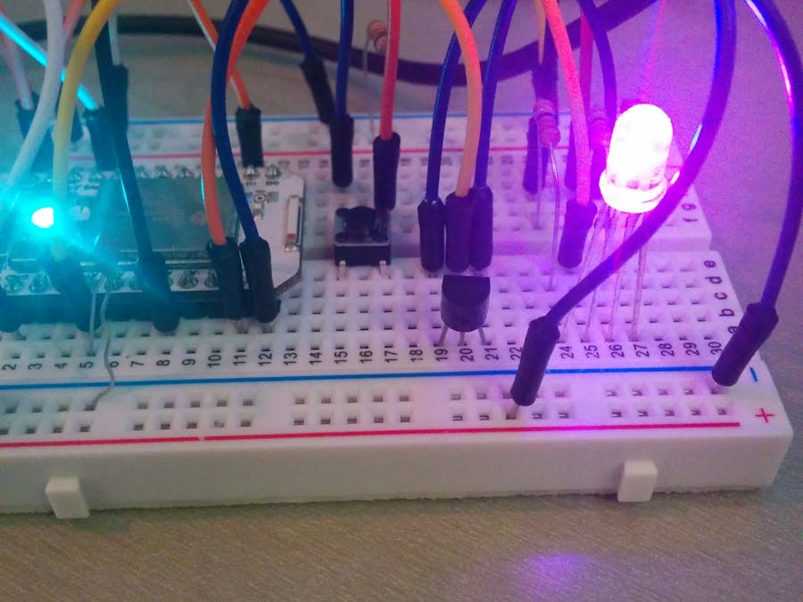
Description
Here is a project one can make with solely components in a Spark Maker's Kit. This project has a RGB LED that has on/off functionality controlled via a push-button, while its color is dependent on a temperature sensor also connected in the circuit. This is a fun project that can introduce one to various components in a Maker's kit, while also to the Spark platform and Web IDE.
Materials List:
Datasheets and documentation on the Maker Kit can be found here at: http://docs.spark.io/shields/#spark-maker-kit
1x Breadboard:
- Used to prototype electronics and circuits. Here is a nice visual of where live connections exist: http://www.backward-workshop.com/wp-content/uploads/2013/05/Breadboard.png
1x Spark Core
- Used as the brains of the operation, runs the firmware, and ensures everything is talking to one another correctly.
1x RGB LED
- Used as the visual component of the thermostat in this example.
1x TMP 36 Temperature Sensor
- Listens to the temperature sending it back to the Core as an analog value via pin A7. If you end up with strange readings a great way to start troubleshooting is here: https://community.spark.io/t/odd-analog-readings-part-2/2718
1x 0.01 uF Capacitor
- Stabilizes the temperature readings. See the link above on temperature/analog readings for detailed information.
1x Push-button
- Uses to control the state of the LED as on/off.
1x 10k Ohm Resistor
3x 330 Ohm Resistor
13x Wire
Construction:
See the Frizting diagram in the pictures widget for reference.
Step 1: Push-button>Place the Spark Core on the edge of the breadboard with the micro USB input facing outwards as in the Fritzing diagram.
On the edges of the breadboard wire the positive rails to 3.3V and the negative rails to ground. These wirings correspond to the red and blue wires on the far right of the breadboard in the Fritzing. Place the push-button in the board so that it has two pins on the top half of the breadboard and the other two on the bottom.
Wire pin D1 to the bottom left side of the push-button (shown by the cyan wire in the Fritzing), and connect this bottom left pin to the 3.3V (+ rail) via a 10k Ohm resistor (Brown-Black-Orange-Gold band pattern; for more info on resistor color codes see http://www.instructables.com/id/Electronics-for-Absolute-Beginners-Chapter-2/). Wire the right side to ground (blue wire from push button to negative rail).
In the code inputPin (the push-button pin) is set to D1 and is additionally set as an input via pinMode() (lines 17 and 42, respectively) in setup(). Thus pin D1 will be reading values in the circuit it is connected to via the cyan wire; the push-button should be pulled HIGH as a default and then should read LOW when pressed.
Now that our push-button is connected, we can have the Spark Core respond in certain ways, depending on whether or not it is pressed (in our case turn the LED on/off).
Step 2: Temperature Sensor>Wire pin A7 to the middle pin of the temperature sensor, with the respective pins connected to 3.3V and ground, (datasheet: http://www.analog.com/static/imported-files/data_sheets/TMP35_36_37.pdf). Pin A7 is an analog pin, and it is set as an input in line 41 of the code. The analog value that is output by the sensor, and read by the pin, is first converted to a voltage and then to a Celsius temperature in lines 50 & 51 of the code.
To stabilize temperature readings connect the 0.01 uF capacitor from pin A7 to ground. Be aware the Core heats up and can skew temperature values; extending the sensor away from the Core may make readings more accurate. See the link in the materials list if unexpected readings occur.
Step 3: RGB LED>Wire the common anode (the longest lead) on the RGB LED to 3.3V + rail (data sheet for the LED : http://docs.spark.io/assets/datasheets/makerkit/rgb-led.pdf), as the yellow wire in the Fritzing does. Wire the individual RGB cathodes to pins A4, A1, and A0 respectively (these are PWM pins so they can write intensities from 0 to 255; not just HIGH or LOW) each through a 330 Ohm resistor. In the Fritzing these connections live in the green, orange, and brown wires respectively. In the code these pins are all set as OUTPUTS (lines 13 - 15).
In this circuit each of the individual pins A4, A1, and A0 act as a ground pin for Red, Green, and Blue--separately and respectively. If one of the pins, say A4, is written to 0, then the respective color--red in this example--will have a full brightness value of 255. If instead it is written to 255, the color will have an intensity of 0 (No current will flow from the 3.3V to A4 as a write of 255 corresponds to 3.3V).
Code:
The code I used for this project is a posted just down the page, under the block titled "Code".
Copy and paste the code into the Spark Web IDE and flash it to your Core: https://www.spark.io/build. Adjusting the tempHigh and tempLow values to suit a temperature range in your current environment may make the changes to the LED much more visible. Open a serial line using the Spark CLI to see your temperature reading, red, and blue intensities for debugging, optimization, or observation. Reference: http://docs.spark.io/cli/
Step 4:You have just created a visual thermostat using the parts included in the Spark Maker kit! See what else you can create, upload it to hackster, and share your creations with us.
For any suggestions or questions feel free to email me at max @ spark.io.
Another great resource for questions is the spark community at community.spark.io


Comments
Please log in or sign up to comment.