


Hardware components | ||||||
 |
| × | 1 | |||
| × | 1 | ||||
| × | 1 | ||||
 |
| × | 1 | |||
| × | 1 | ||||
| × | 1 | ||||
| × | 1 | ||||
| × | 1 | ||||
| × | 1 | ||||
| × | 1 | ||||
Software apps and online services | ||||||
 |
| |||||
Hygrometer sensors are often used for "smart garden" projects. However, what many do not take into account is that they are known for quickly corroding, at least the simple and affordable ones. Particularly if watering is required every day, it makes sense to use a real time clock (RTC) instead. This is the underlining idea behind this project.
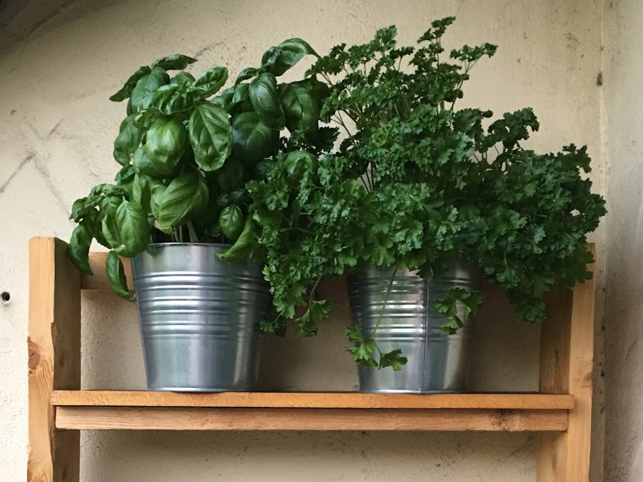
The Herbal Garden ShelfMy herbal garden shelf is hanging at a wall on my balcony (see picture 1) and in summer I have to water the herbs twice a day, preferably at 6 in the morning and somewhen close to sunset. There are two problems I have came across over the past years. First, I tend to forget to water my herbs and in case I remember to do so, it is mostly at a time not convenient for the plants. Therefore, an RTC-controlled auto watering seems a perfect solution.
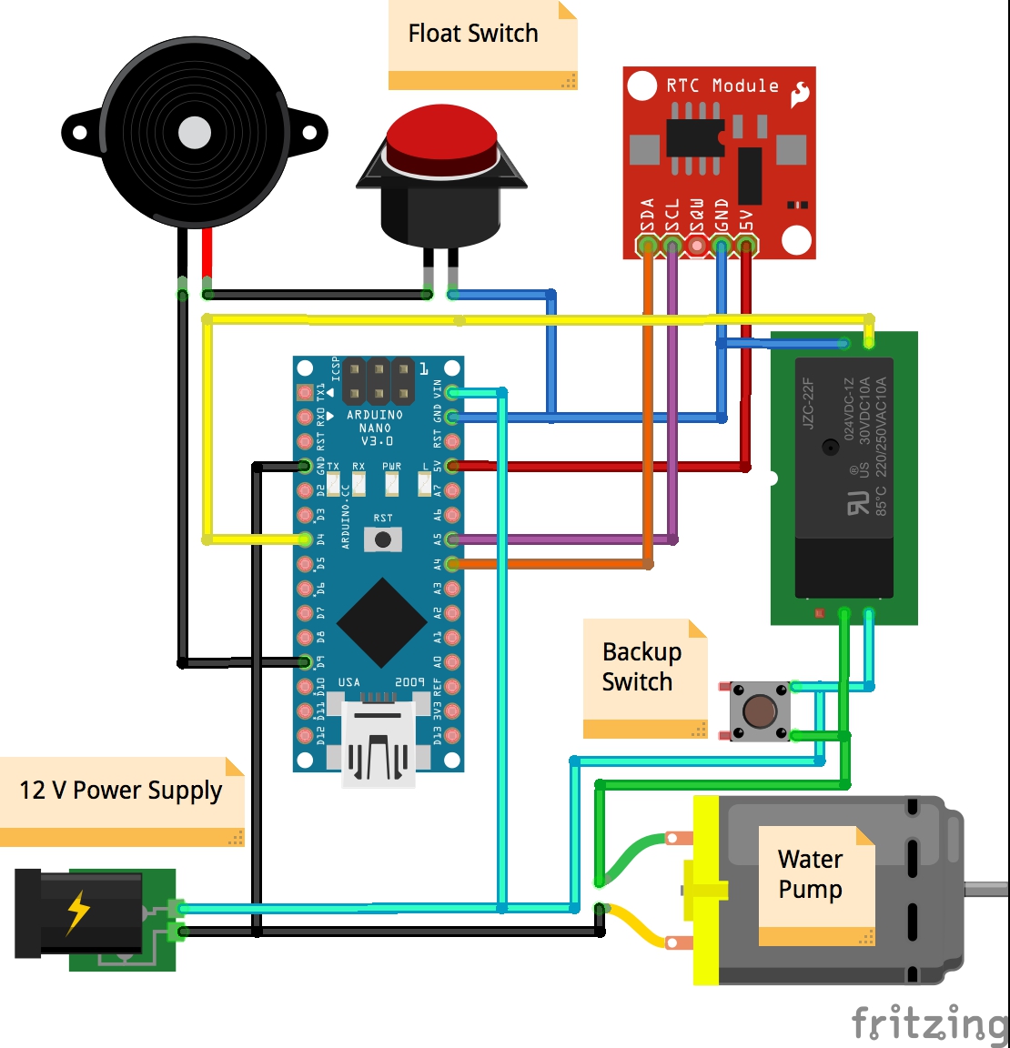
As the whole watering system sits outdoors and uses a 230 V power supply, a weatherproof box is needed to keep the electronics and the circuit nicely protected. Picture 2 shows the weatherproof electric box filled up with the equipment: multi way connector, 12V power pack, real time clock, relay, buzzer, and Arduino Nano. I am using an Arduino Nano because it is smaller and takes less space in the box. Picture 3 shows the weatherproof electric box when closed and in use.
The water supply is enabled through a 20 liter tank, enough to keep the watering running for a few weeks (picture 4). As visible in picture 5, there are two yellow cables leaving the water tank on the bottom. Those are connected to a float switch, that triggers an alarm if the water level goes below 4 cm, a critical level for the pump. The circuit schematics at the bottom do not show the float switch as a proper symbol. The reason is because there was no such device available on fritzing. The pump is connected to the relay, 12V power and a 12mm PVC tube.
The watering system is made with aquarium equipment that can be purchased online or in a local aquarium shop. NOTE the individual watering parts (tubes, angels, and valves) are not included in the component list above because this really depends on the quantity of herbs involved. Nevertheless, a brief explanation is given in the following paragraphs.
The watering system starts with a 12mm tube that leaves the pump. Picture 6 shows an adapter connecting the 12mm pump tube to a 4/6 mm aquarium air tube.
As visualized in picture 7 and drawing 1, there are a number of corners and branches along the watering system. One can either use plastic materials or stainless components, which look nicer but cost a few Euros more.
Each watering exit is connected to a small valve that allows customizing the quantity of water due to slightly different water pressure levels on each exit (Picture 8 and 9). As visible in the circuit schematics below, a backup switch is connected to the pump, which can be pressed in order to adjust the valves at each watering point.
The code for the relay/RTC is from the Robot Geek Team on the Arduino Project Hub and the code for the buzzer is from a codebender tutorial from the Instructables platform. Both are combined in a single sketch. The RTC triggers the relay during a specific hour each day: 6 in the morning and at 8 in the evening. The relay is then powered for 20 seconds followed by a long delay. This is necessary because the real time clock is triggering action during the entire hour, in other words from 8:00 to 8:59. Thus after 20 seconds of watering a 3600 seconds delay keeps the relay powered off during the entire hour.
I am well aware that there might be much more elegant solutions to the given problem. However, as I am still at the beginning of programming, I was satisfied with that solution because it does what it is supposed to.
The alarm is set on a 2000 HZ level. This is loud enough to be heard inside the house. Meanwhile it avoids disturbing any neighbors.
SchematicsThis project uses an Arduino Nano shield or terminal adapter (see hardware list) coming with screws for every pin to ensure proper connection. For all other connections this project uses socket terminals. There are probably more professional solutions, but this one makes sure each connection keeps stable even in case someone accidentally bumps against the weatherproof box. This is the reason why the schematics do not show any breadboard.


Comments
Please log in or sign up to comment.