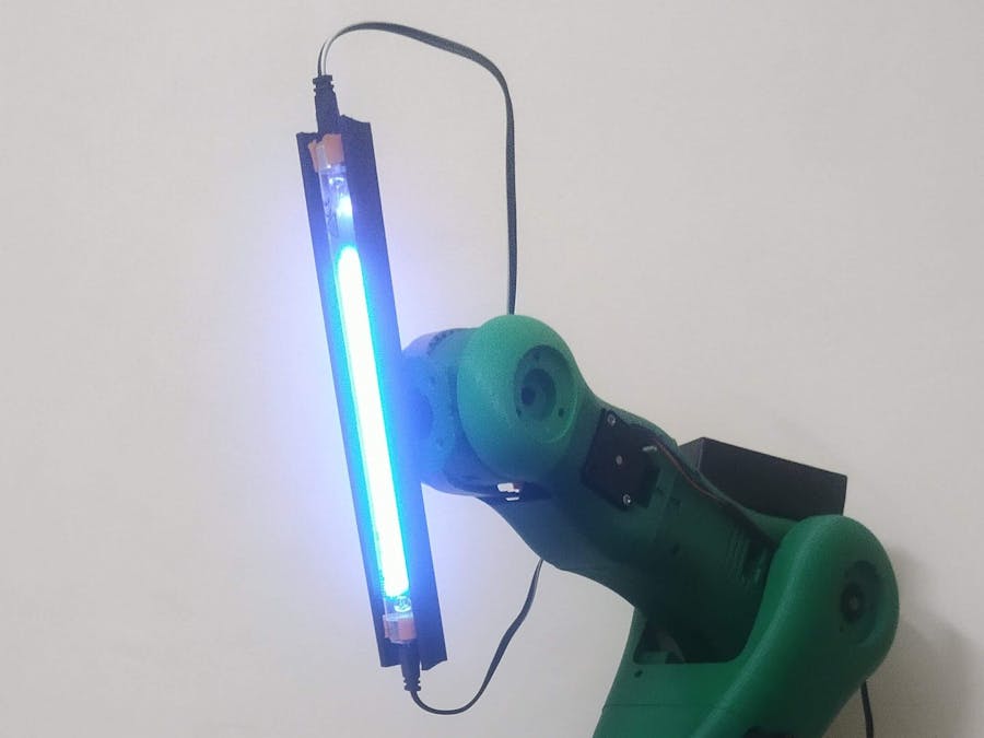
I wanted to build a robotic arm to be used in sanitation process. As robotic arm has more control and reach as compared to simply using uv rods horizontal to robot design frame. In the story have build the robotic arm from open source 3d designs and of the shelf components. Most of the 3d printed parts can be printed on 220 x 220 mm bed size printer.
For BASIC navigation and obstacle i have planned on using the rplidar A1m8 and raspberry pie.
The 8'' UVC bulb i have used are taken from RO filters to kill germs and clean water It also require a AC powered choke to work.
In order to power the entire system I have used 12 volt 35 AH car battery and which s heavy and need to taken into consideration in design process.
UVC RO bulb that need a ac power source the choke needs Ac source I have used product from local manufacture in india Quantico 300W Heavy Duty Car Inverter12v dc to 220Ac. Here is list of product's from amazon that can be ordered based on you country keep in mind the AC circuit will only work if you have steady power supply, Hence lead acid car battery is the source.
I have used the 3d printed robotic arm from BCN3D MOVEO and the modified the parts according to my needs.
The basic firmware is marlin 2.0 and also changed as per my needs In order to power all 4 axis (5 stepper motors <two on shoulder>) I have used the RMAPS 1.4 Board and 4 A4988 stepper drivers. Ramps board helps me to power two Shoulder stepper motor using single driver in ramps board.
The entire build process is divided into three parts.
- The Base chassis to mount entire platform.
- The 3d printed robotic arm and assembly.
- The UVC light mounting and powering the circuit.
The Base chassis to mount entire platform.
i have chosen Wood as basic frame to mount the assembly
The code to control the 4 motor using h bridge and flysky fs-i6
int enB = 5;
int in3 = 3;
int in4 = 4;

int enA = 10;
int in11 = 11;
int in12 = 12;

int channe6_3 = 6; // the throttle. channel 3 on pin 6
int channe7_1 = 7; // the throttle. channel 1 on pin 7
int channel2 = 10;// to pins 9 and 10 of arduino respectively

int Channel1 ; // Used later to
int Channel2 ; // store values

void  setup ()
{

  pinMode(enB, OUTPUT);
  pinMode(in3, OUTPUT);
  pinMode(in4, OUTPUT);

  pinMode(enA, OUTPUT);
  pinMode(in11, OUTPUT);
  pinMode(in12, OUTPUT);

  pinMode (channe6_3, INPUT);// initialises the channels as input
  pinMode (channe7_1, INPUT);// initialises the channels as input

  digitalWrite(in3, LOW);
  digitalWrite(in4, LOW);
  digitalWrite(in11, LOW);
  digitalWrite(in12, LOW);

  Serial.begin (9600); // Sets the baud rate to 9600 bps
}

void  loop ()
{
  Channel1 = (pulseIn (channe6_3, HIGH)); // Checks the value of channel1
  Channel2 = (pulseIn (channe7_1, HIGH)); // Checks the value of channel1

  ////////////throttle////////////////////////////////
  Serial.print("throttle value:-");
  Serial.println (Channel1); //Prints the channels value on the serial monitor
  ////////////Steering////////////////////////////////
  Serial.print("***************************\n");
  Serial.print("steering value value:-");
  Serial.println (Channel2); //Prints the channels value on the serial monitor

  //steering value left:-1220 right:- 1700

  if ( Channel1 < 1100 ) /*If these conditions are true, do the following. These are the values that I got from my transmitter, which you may customize according to your transmitter values */
  {
    Serial.println ("slow speed");
    backward();
  }
    if (Channel1 > 1700  ) /*If these conditions are true, do the following. These are the values that I got from my transmitter, which you may customize according to your transmitter values */
  {
    Serial.println ("high  speed");
    forward();
  }

    if ( Channel2 < 1100 ) /*If these conditions are true, do the following. These are the values that I got from my transmitter, which you may customize according to your transmitter values */
  {
    Serial.println ("steer left speed");
    left();
  }
    if (Channel2 > 1600  ) /*If these conditions are true, do the following. These are the values that I got from my transmitter, which you may customize according to your transmitter values */
  {
    Serial.println ("steer rightt  speed");
    right();
  }
  delay(1000);

 }// end of block
void left()
{
  analogWrite(enB, 255);
  analogWrite(enA, 255);
  // Turn on motor A
  digitalWrite(in3, LOW);
  digitalWrite(in4, HIGH);
  // Turn on motor B
  digitalWrite(in11, LOW);
  digitalWrite(in12, HIGH);
  delay(2000);
  // Turn off motors
  digitalWrite(in3, LOW);
  digitalWrite(in4, LOW);
  digitalWrite(in11, LOW);
  digitalWrite(in12, LOW);
  }

 void right()
{
  analogWrite(enB, 255);
  analogWrite(enA, 255);
  // Turn on motor A
  digitalWrite(in3, HIGH);
  digitalWrite(in4, LOW);
  // Turn on motor B
  digitalWrite(in11, HIGH );
  digitalWrite(in12,LOW );
  delay(2000);
  // Turn off motors
  digitalWrite(in3, LOW);
  digitalWrite(in4, LOW);
  digitalWrite(in11, LOW);
  digitalWrite(in12, LOW);
  }
void forward(){
  analogWrite(enB, 255);
  analogWrite(enA, 255);
  // Turn on motor A
  digitalWrite(in3, HIGH);
  digitalWrite(in4, LOW);
  // Turn on motor B
  digitalWrite(in11, LOW);
  digitalWrite(in12, HIGH);
  delay(2000);
  // Turn off motors
  digitalWrite(in3, LOW);
  digitalWrite(in4, LOW);
  digitalWrite(in11, LOW);
  digitalWrite(in12, LOW);
  }
void backward(){
   analogWrite(enB, 255);
  analogWrite(enA, 255);
  // Turn on motor A
  digitalWrite(in3, LOW);
  digitalWrite(in4, HIGH);
  // Turn on motor B
  digitalWrite(in11, HIGH);
  digitalWrite(in12, LOW);
  delay(2000);
  // Turn off motors
  digitalWrite(in3, LOW);
  digitalWrite(in4, LOW);
  digitalWrite(in11, LOW);
  digitalWrite(in12, LOW);
  }
The chassis was working fine up until 6-7 kg but later the overall size of entire frame+battery and robotic arm was more than 9 kg. That restricted the robot chassis to move 360 Degree.
The 3d printed robotic arm and assembly.
I have printed all my parts on my Ender 3 printer But you can use any printing service. The T5 pulleys are also 3d printed to save money
The UVC light mounting and powering the circuit.
Mounting UCV bulb on arm
Problems and challenges faced:-
The torque of dc motor is is not enough after the build to make turn or rotate, I needed to upgrade to motor of higher torque which is not possible in current conditions and given time.
Let me know in the comments about your thoughts and suggestions


_wzec989qrF.jpg?auto=compress%2Cformat&w=48&h=48&fit=fill&bg=ffffff)


Comments
Please log in or sign up to comment.