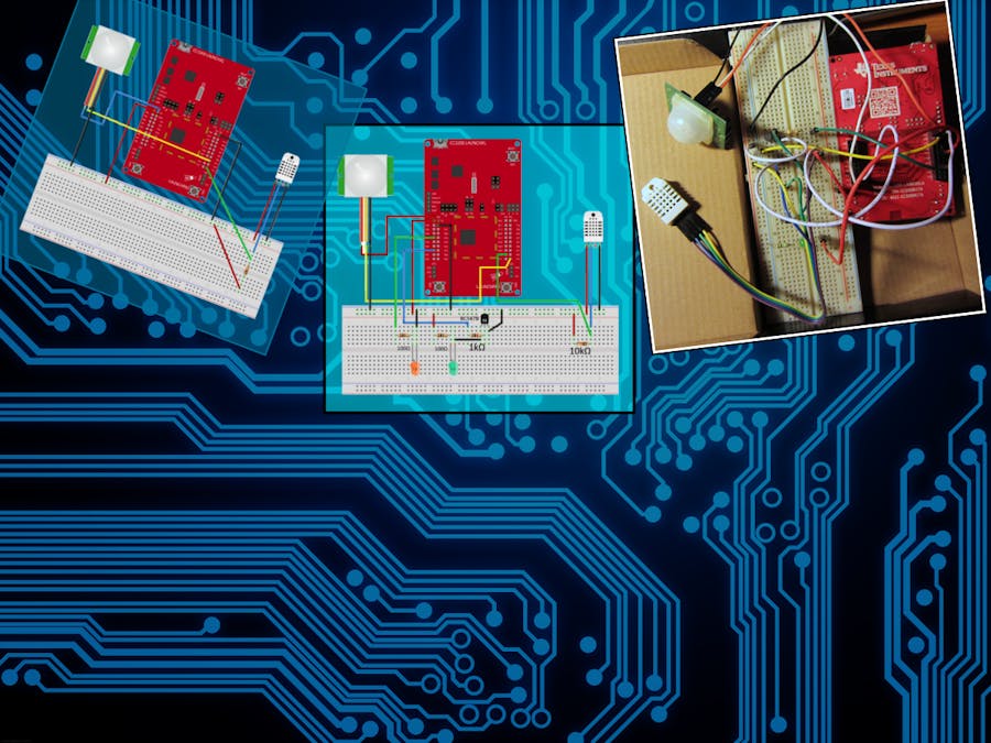
Device monitors your presence in the room using PIR-sensor. If there's movement near the device and mailbox monitored by backend application has new email, then the device will light up. If there's no movement detected by the device in predefined time window, lights will be dimmed out to minimize light pollution in the room. As an added bonus the device sends room temperature and humidity to server while polling for email state.
This contraption uses CC3200 launchpad as controller, amazon IoT MQTT service and small PHP backend application to monitor email boxes.
Part 1 - Amazon IOT:To recreate this project, you should begin by registering account from amazon aws. After you have created account and it has been activated, you can create IoT solution like this:
- Image 1: select region and go to IoT service tab .
- Image 2 & 3: Click "create a resource", and then create "thing" called "cc3200".
- Image 4 & 5: For the board to access AWS IoT services, you need to create new certificate. After clicking "1-click create" remember to save certificate and keys as they can't be accessed again after this. I'm going to refer these files as "cc3200.crt" and "cc3200.key".
- Image 6: Click create new policy, fill in the values as in the picture then click "add statement" and create.
- Image 7: After completing steps 1-6 your view should look something like this
- Image 8: Select the thing you create in step 2 and take note of the API endpoint as you need to set it in the config.h files for both backend and CC3200 application.
- Image 9: Now select the certificate you create, click actions and activate. After that you can attach policy and thing to the certificate (images 10 & 11)
Last step is to download rootCA for AWS IoT. Currently the certificate pem file is found on this address: https://www.symantec.com/content/en/us/enterprise/verisign/roots/VeriSign-Class%203-Public-Primary-Certification-Authority-G5.pem
Part 2 - PHP backend:Running the backend application requires at least 5.5 version of the PHP cli to be installed. PHP should also have imap, SSL and sqlite support compiled in.
Once you have installed proper version of PHP, download the code repo from GitHub and navigate to "phpBackend" - directory. Fill in "config.php" file with your email servers imap settings and AWS certificate details (cc3200.crt, cc3200.key). Note: I'm using the same certificate for both backend and device. You can either use this model, or create own certificate and key for every client.
If everything is set up correctly, running the script with command "php backend.php" should check your mailbox for new emails, create sqlite database file for temperature/humidity readings and send status notification to AWS IoT service. Script keeps on running as long as it's killed or you press CTRL+C.
Also note that the script is mostly proof of concept, so error checking and handling is left as an exercise.
Part 3 - CC3200 board jumper settings:This project needs the board configured as in the picture below:
- (1): As the project doesn't use onboard sensors, remove jumpers. This also allow the program to control the green and yellow leds.
- (2 & 3): To program the board with Energia IDE, connect jumper wire between pins show on notes 2 (J15 lower pin) and 3 (J8 upper pin). But connect the jumper only after you have updated firmware with uniflash (see next chapter).
- (4): Jumper between VCC and p58 pins forces the network chip to AP mode, so remove it, if it's in place.
I'm using Fedora Linux 23 to program the board with Energia 17 (fork of Arduino for launchpad boards), but certificates need to be programmed using Uniflash tool (link in software section), which only runs on windows.
Convert Amazons root CA, cc3200_crt and cc3200_key from PEM format to DER format then program them to board using uniflash. Also update boards bootloader, if not done already.
Now you can switch back to Linux, or keep using Windows. Either one will work as Energia is available to both platforms. Remember to edit "config.h" file, before programming the board.
When you boot up the board, you can follow the status of the application via serial interface, or looking at the leds:
- Yellow led lights up when the application is in setup loop and closes when the setup is completed
- If red led starts to blink, it means that the application is unable to connect to network and is unable to continue.
- Debug led (if connected) lights up, when the device has detected motion and is accepting "new mail" commands from MQTT.
Ps. If you need help on using Uniflash, or programming board with Energia, please see the last chapters on my article: http://www.mcfish.org/blog/8-cc3200-energia-mosquitto
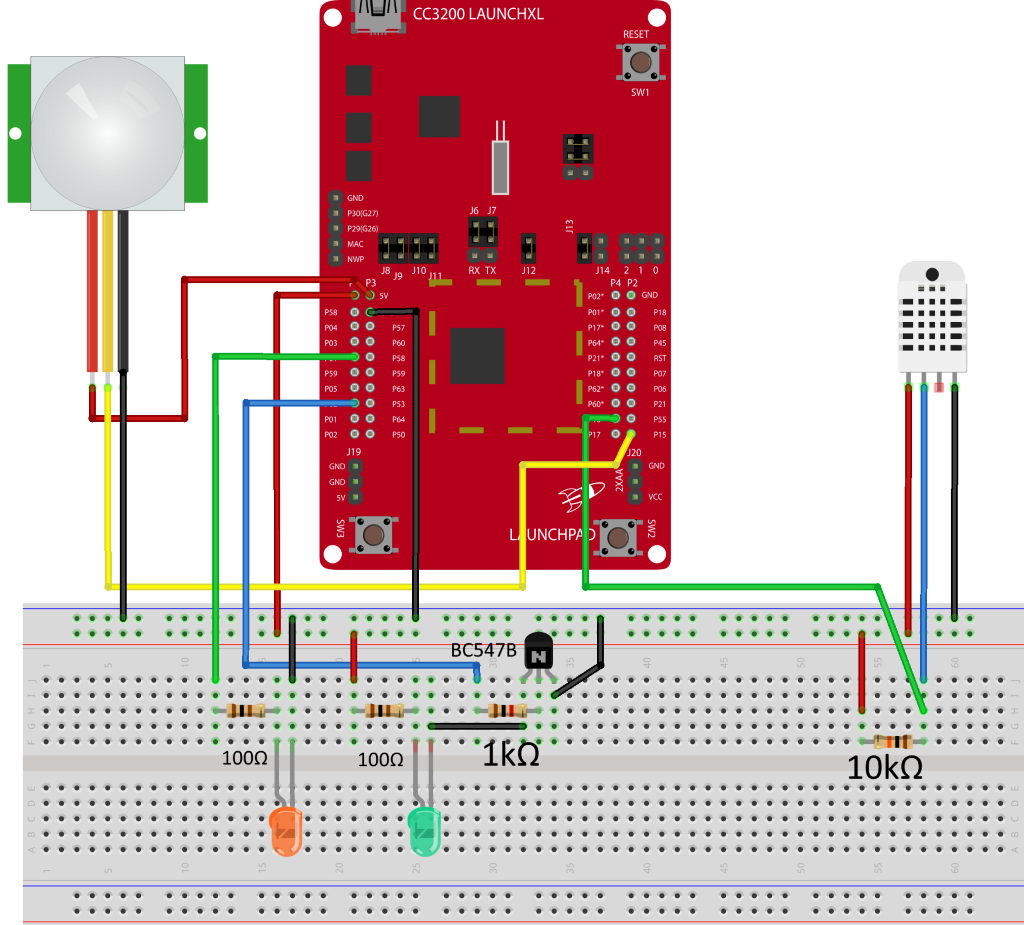
Part 5 - Schematics:Connecting sensors to board is quite simple:
- Seeedstudios PIR sensor needs 5v to run, so connect it to main power bus (which in turn is connected directly to 5v from USB).
- DHT22 runs on 3.3v voltage, so it can be connect to regulated power bus. Also there needs to be resistor (10kΩ) between DHT22 sensors data pin and 3.3v pin. This is so called pull-up resistor, which keeps the line at high state.
- Load (one green led in this case) is driven using NPN-transistor (BC547B) switch to prevent it overloading the chips output. Resistor between transistor base and output pin is 1kΩ and the current limiting resistor for led is 100Ω.
- Orange led on the board is just for debugging motion sensor. You can leave it out from your prototype if you like. Remember also to comment it out from setup.h in CC3200 code.
When done, the prototype spaghetti monster should look something like this:
To make the project fit to a smaller container, a printer circuit board is needed. I'm using KiCad 4.0.1 to design the board and Seeedstudios PCB service to manufacture it. As the minimum number of board that gets manufactured is 10 pieces, I decided to design a more universal protoboard as I have no need for 10 of these devices.
This board fits over CC3200 and allows easy access to all pins. Inner header places are routed to actual board pins, so it's easier to connect jumper cables to the board itself. Also the board has rails for GND and +3.3v power supply.
This is the first version sent to production, so design might need some improments. But feel free to play around with attached KiCad project files.


Comments
Please log in or sign up to comment.