mcharrison500
Published

Ultrasonic Sensor with LCD Display Using 433MHz

Display the results from the HC-SR04 ultrasonic sensor on an LCD display using 433MHz transmitter and receiver.

BeginnerFull instructions provided38,529
Ultrasonic Sensor with LCD Display Using 433MHz

Things used in this project

Story

Read more

Schematics

LCD Flowchart

Ultrasonic sensor (RECEIVER)

Code

Ultrasonic sensor (TRANSMITER)

Arduino
I selected the UNO for this part because it can be powered by an external source.
First connect the GND and the VCC from the Arduino to the bread board
Insert the LM35 on the breadboard and connect the GND and the VCC.
Insert the RF433-TX module, place it facing you and Pins should be DATA, VCC, GND from left to right

Connect the VCC and the GND to the +/- rails on the breadboard and the Data pin connects on digital pin 12 on the Arduino.
#include <VirtualWire.h> //Load the library

const int trigPin  = A0;
const int echoPin  = A1;
float duration, distance;     
char msg[6];


void setup()
{
    vw_set_tx_pin(12);          // Sets pin D12 as the TX pin
    vw_setup(2000);	        // Bits per sec
    pinMode(trigPin, OUTPUT); 
    pinMode(echoPin, INPUT); 
    Serial.begin(9600); 
}

void loop()
{
     digitalWrite(trigPin, LOW); 
     delay(500); 
    digitalWrite(trigPin, HIGH); 
     delay(500); 
    digitalWrite(trigPin, LOW); 
    duration = pulseIn(echoPin, HIGH);
    distance = (duration*.0343)/2; 
    Serial.print("Distance: "); 
    Serial.println(distance);     
    dtostrf(distance, 6,2,msg);           //converts the float into a char 
    vw_send((uint8_t *)msg, strlen(msg)); //transmits the data
    vw_wait_tx(); // Wait until the whole message is gone
    delay(500);
 }
 

receiverLCD

Arduino
I will connect the NANO with the LCD and the RF433-RX module
Plug in the NANO on the breadboard

Then insert the RF433-RX module

Connect the VCC and the GND from the RF433-RX to the NANO GND and VCC and connect the Data PIN (left most pin) to the digital pin 12 on the NANO

Connect the GND and the VCC from the I2C serial LCD to the GND and the VCC pins on the NANO, then connect the SDA to analog pin 4 on the NANO and the SCL to analog pin 5 on the NANO.
//load libraries
#include <VirtualWire.h>
#include <Wire.h>
#include <LCD.h>
#include <LiquidCrystal_I2C.h>

//Define variables 

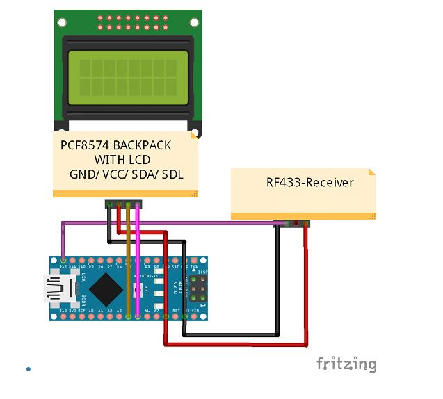
#define I2C_ADDR          0x3F       //Define I2C Address where the PCF8574A is
#define BACKLIGHT_PIN      3
#define En_pin             2
#define Rw_pin             1
#define Rs_pin             0
#define D4_pin             4
#define D5_pin             5
#define D6_pin             6
#define D7_pin             7

//Initialise the LCD
LiquidCrystal_I2C      lcd(I2C_ADDR, En_pin,Rw_pin,Rs_pin,D4_pin,D5_pin,D6_pin,D7_pin);

int i;    //and integer used to count

void setup()
{
    //Define the LCD as 16 column by 2 rows 
    lcd.begin (16,2);
    
    //Switch on the backlight
    lcd.setBacklightPin(BACKLIGHT_PIN,POSITIVE);
    lcd.setBacklight(HIGH);
    
    //Define the receiver pin and rate
    vw_set_rx_pin(12);       //Sets pin D12 as the RX Pin
    vw_setup(2000);	     // Bits per sec
    vw_rx_start();           // Start the receiver PLL running
}

void loop()
{
   uint8_t buf[VW_MAX_MESSAGE_LEN];
   uint8_t buflen = VW_MAX_MESSAGE_LEN;
   
   if( vw_get_message(buf, &buflen) )
      {
        lcd.setCursor(0, 0);
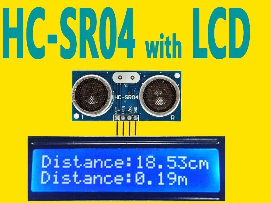
        lcd.print("distance is:");    
        lcd.setCursor(3,1);  
        
       for (i = 0; i < buflen; i++)
         { 
           lcd.write(buf[i]); 
                    
         }
        
           lcd.print((char)223);
           

      }
 
}

Credits

mcharrison500

mcharrison500

1 project • 8 followers
Ambitious 4th year student of BEng (Hons) Software & Electronic Engineering at Galway-Mayo Institute of Technology (GMIT).

Comments