


Hardware components | ||||||
 |
| × | 1 | |||
| × | 1 | ||||
 |
| × | 1 | |||
 |
| × | 1 | |||
Hand tools and fabrication machines | ||||||
 |
| |||||
 |
| |||||
Recently, I set out on a mission to find an integrated circuit (IC) that could serve as a timer. After an extensive search (and more than a few cups of coffee), I stumbled upon the CD4047—a real gem with a plethora of features. This IC isn’t just a timer; it offers multiple modes, highlighting its versatility. These additional functionalities make the CD4047 an indispensable tool for rapid prototyping, adaptable for various applications beyond simple timing. Its flexibility and user-friendly nature streamline the development process, making it a favorite in many electronic projects.
In this article, we'll explore how to create a timer using the CD4047 as a monostable multivibrator. Get ready to be impressed by its capabilities and ease of use!
PINOUT OF CD4047:
The pinout of the CD4047 is elegantly depicted in the image above. The straightforward explanation makes it a snap to identify and use each pin for different applications. This comprehensive diagram helps users quickly understand the functionality and connections needed for the effective use of the IC, making your project setup as easy as pie!
CIRCUIT OF MONOSTABLE MULTIVIBRATOR:
The Monostable function, as its name suggests, has one stable state that shifts to an unstable state when triggered externally. After a set period, it reverts back to its stable state, making it a popular choice for timers in various applications. While modern microcontrollers offer more features, the CD4047 shines with its speed, efficiency, reliability, and cost-effectiveness for specific tasks.
The CD4047 actually offers up to four modes for Monostable Multivibrators. We'll begin with the first mode: Positive Edge Trigger Mode.
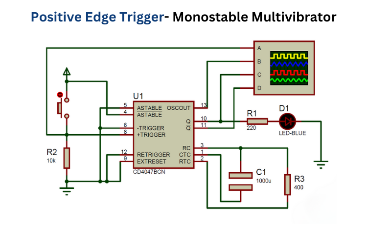
The circuit diagram above shows the configuration for the CD4047 IC in Positive Edge Trigger Mode. Here's a breakdown of the key connections:
- Pins 4 and 14 to +5V.
- Pins 5, 6, 7, 9, and 12 to Ground.
- A 1000µF capacitor between Pins 1 and 3.
- A 400Ω resistor between Pins 2 and 3.
- An LED with a 220Ω resistor connected to Pin 10 (Q).
- Pin 8 (+TRIGGER) connected to +5V via a pushbutton and pulled down with a 10kΩ resistor.
- An oscilloscope connected to Pins 8, 10 (Q output), 11 (\(\overline{Q}\) output), and 13 (OSC output) to observe waveforms and timing.
Ready to dive in? Let's get started!
Calculation of Delay Time:
Calculating the timing (tM) for all modes in the Monostable Multivibrator is straightforward with the formula: tM = 2.48 x R x C.
For instance, if you're using a 1000µF capacitor and a 400Ω resistor:
tM = 2.48 x 400 x 1000µF = 0.992 sec
So, you can round it up and call it 1 second—close enough for most purposes!
Using this formula, you can easily pick the right resistor and capacitor values to achieve your desired timing. No need to overthink it; just plug in the numbers and you're good to go!
Circuit Connections and Validation :According to the circuit diagram, all connections were meticulously made as specified. Before diving into real-world implementation, we simulated the entire setup in Proteus. This thorough simulation ensured that all connections were accurate and the circuit functioned as intended. Such preemptive validation boosted our confidence in its real-world application. The subsequent successful breadboard implementation further confirmed the design's accuracy, perfectly mirroring the Proteus simulation results.
ConclusionWith the project requirements in hand, the Timer Project has been successfully completed. While we've explored several modes, there are still six more to uncover. For those eager to dive deeper, we’ve put together an article detailing the CD4047's Astable and Monostable Multivibrator modes. You'll find a wealth of information on waveforms and simulation results, providing a comprehensive understanding. Want to expand your knowledge and enhance your projects? Check out the video below for valuable insights and practical guidance.


_3u05Tpwasz.png?auto=compress%2Cformat&w=40&h=40&fit=fillmax&bg=fff&dpr=2)
Comments
Please log in or sign up to comment.