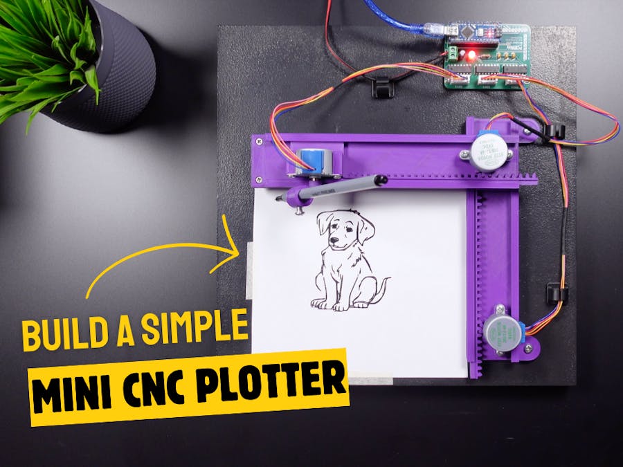
Hi friends, we will see how to make a simple and awesome mini CNC plotter machine in this project. I saw this project on Thingiverse a few days ago and found it very interesting, so I prepared a video with all the steps.
Step 1: 3D Parts and AssemblyThe project is based on Arduino and includes GRBL code. It contains 3 hobby stepping motors and 3D parts that provide movement in 3 axes. I start the first step of the project by assembling the 3D parts and stepping motors that make up the main structure of the project. 3D models are printed in medium quality without support and the required screw types vary, you can use the compatible size in your workshop.
I have updated 2 of the 3D parts to make them more compatible. You can access all original parts from this link - https://www.thingiverse.com/thing:4607077
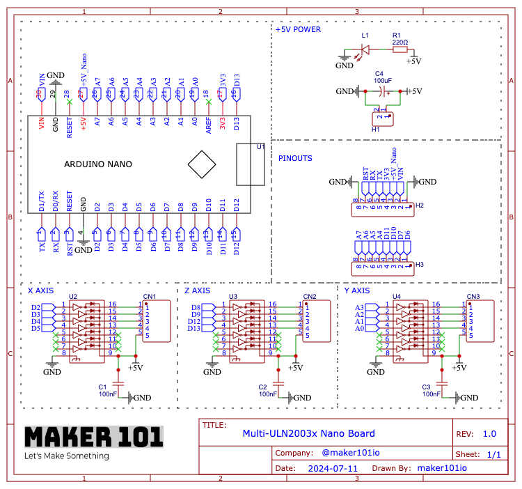
Step 2: The CircuitThe circuit part of the project requires one Arduino Nano and three stepper motor drivers. You can build the project on a breadboard following the shared circuit diagram. But as you know, I prefer to design and use a printed circuit board for a more professional prototype. I share my printed circuit board designs as open-source on the PCBWay project sharing page. You can also choose PCBWay for low-price and high-quality printed circuit boards. Let's continue by assembling and soldering the components used in the printed circuit board.
Step 3: Complete the AssemblyAfter soldering, let's assemble the circuit board to the project. Each axis input is marked on the circuit board, make the connections, and plug in the Arduino board. The circuit must be supplied with external 5-volts, make the power connections, and then attach the pen and paper to the project. Finally, make the USB connection and start the power.
Step 4: ProgrammingThe programming part is very simple, first download and install the previous version of the Arduino IDE 1-8-5.
- Download the GRBL library from the shared GitHub link.
- Open the Arduino editor and include the downloaded library.
- Then open the code named GRBL Upload from the examples section, you do not need to make any changes here, just upload the code by selecting the board and port.
At this stage, we will create a vector image using Inkscape. Download the required version from the shared link, install it and open Inkscape.
- Then go to the document properties and enter the page size dimensions.
- Import any image of your choice, adjust the image size accordingly and place it on the page.
- Then convert the image to vector and delete the previous inserted image.
- Now the vector image is ready for drawing, save the created image.
We will use the JSCut web tool to convert the vector file to G-code. The interface opens with predefined settings, download and upload the file containing the project settings shared on the PCBWay project page (I could not attach it because the file extension is not supported here). Then, mark it to return to the zero point at the end, and adjust the pen tip width. Load the vector file, select it, and choose to create operation, there are several types of conversion options, choose the one that works for you, and click generate. Finally, save and download the g-code.
Step 7: UGS Platform (G-code Sender)In this section, download and launch G-code Sender, the main software that allows you to configure and control the plotter. First, open the setup wizard, select GRBL as firmware, select the connected port and serial communication, and click connect. The plotter will connect without any problems. In the motor wiring section, you can check if the motors are moving in the opposite direction and make changes. In this plotter, the Y axis will move in reverse. The calibration section allows you to set the initial position of all axes by moving them precisely. Update the calibration section millimeter values for this plotter with the values on the screen (100, 100, 50). You can then move the plotter axes and complete the update with the 'Reset to Zero' button when you reach the optimal positioning. Then press the Finish button and the plotter start position will now be defined.
Import the generated g-code and update the values in the bottom left corner by entering the values on the screen (0, 991 - 0, 991 - 15, 113). These values are the default values that are compatible with the stepper motors used in the plotter. If everything is ready, you can start the printing process by simply pressing the Send command. I hope this was useful, thanks for reading.


Comments
Please log in or sign up to comment.