


Hardware components | ||||||
| × | 1 | ||||
 |
| × | 1 | |||
 |
| × | 1 | |||
 |
| × | 1 | |||
 |
| × | 1 | |||
 |
| × | 1 | |||
Software apps and online services | ||||||
 |
| |||||
This project showcase the new module from Wiznet Wi610io in a web camera application using the Spresense technology by Sony. Using the new W6100 device from Wiznet offers many advantages over the previous recent module W5100 such as IPv6 and more robust SPI interface.
The SetupThe Sony Spresense board doesn't have an Ethernet peripheral which is something we need for the web camera project. There might be many options out there to provide Ethernet connectivity but not all might serve for our purpose, been the speed and large amount of data transfer our makers that need to be maximized.
Based on previous design using W5100 module, I have found Wiznet modules great for the Job, but the nifty W6100 module is very handy to get a camera from anywhere using IPv6. Another advantage of using Wiznet w6100 IC is the easy implementation from Hardware and Firmware perspective. The last is specially true when using the Arduino IDE.
For the video stream we need the Spresense module with the Main board and camera module, for the Wiznet module we have choose Wiz610io but any W6100 based board will work.
Hardware HookupThe Spresense SPI port that uses Arduino IDE is accessible using the Main board and has some limitation in speed compared to Wiz610io module which can be clock up to 70MHz. On our previous work using Wiz550io module, due to a impedance mismatch there was not possible to connect directly the wiznet module to the main CPU board. For Wiz610io module the problem don't exist anymore. Actually we have a running demo using 30MHz SPI clock.
SPI4 is the port used by Spresense Arduino core and is located in the normal position you would find SPI for Arduino Uno R3. Signal line connections are similar to Arduino. One important difference is that Arduino wiznet library uses an I/O to drive the Chip Select pin. This is the suggested way to drive SPI for W6100 IC since CS signal should be active low during a transfer that might consist of several byte cycles. Because of this reason, we cannot connect the CS pin 10 of Spresense, normally labeled SS for arduino pinouts, as this pin is automatically handle by SPI4 peripheral of CXD5602 MCU, this is explained in section 3.8 of Spresense arduino developer guide.
Here is the Wiz610io pinout for reference, but more info here.
The connections end up been:
Spresense MOSI (D11) -> Wiz610io J1 - pin 3
Spresense MISO (D12) -> Wiz610io J2 - pin 6
Spresense SCK (D13) -> Wiz610io J1 - pin 4
Spresense SCS (D8) -> Wiz610io J1 - pin 5
Notice that we leave D10 open and use D8 for CS. This will require some change in arduino firmware library or sketch.
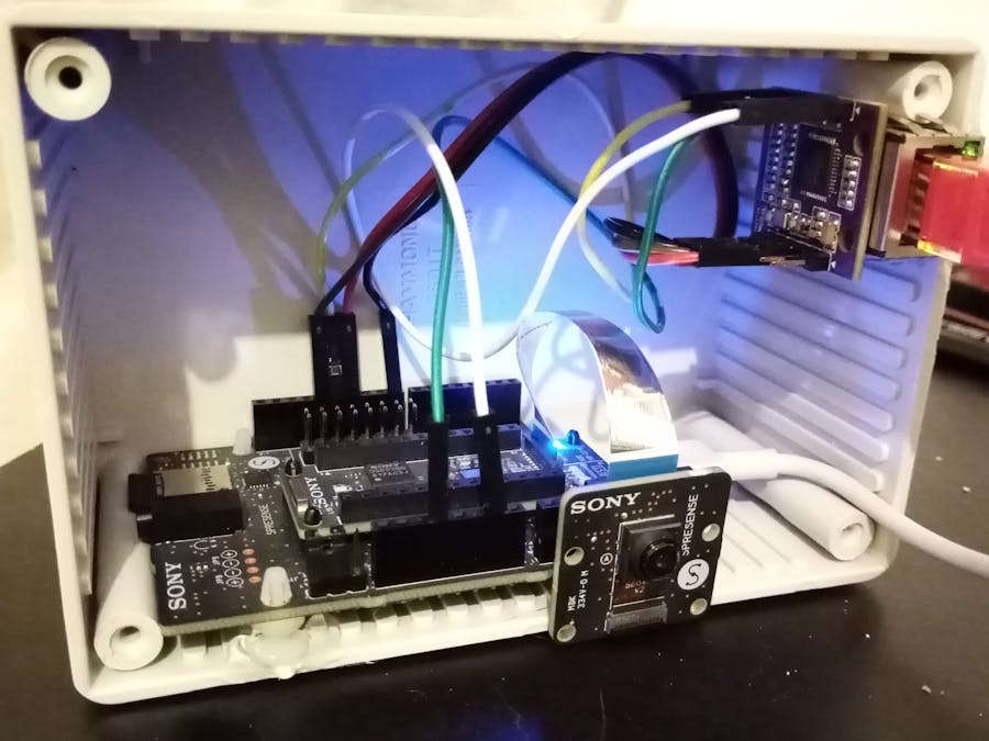
The firmware application needs and SD card as well as camera module connected. To be able to handle the setup for the demo, we have placed the Wiznet module and Spresense board in a box as shown below.
FirmwareThe firmware uses arduino IDE and all the capabilities of Spresense to capture images from camera board. Different libraries are used to send the data over websockets and HTML to the client.
Ethernet Library Firmware
Original library can be found here. There wasn't many changes to make Spresense work with this library, but enough to delay your anxious willing to do some tests after the really simple hookup done before. A list of changes is explained below
- CS need to change - This can be done using library call in sketch but for safety I also change the default in case User miss it.
- Enable the use of large buffers by un-commenting ETHERNET_LARGE_BUFFERS definition.
- The Spresense SPI transfer method has somehow different prototype, so I adjust it accordingly. Look for #ifdef SPI_HAS_TRANSFER_BUF in sources but mainly the write function has the usage.
- Some cast issue with IPAddress. Look for IPAddress((uint32_t)0ul) in source.
- The getSockNum function was added to EthernetClient for compatibility with the web sockets library.
- Serial.printf was added to Hardware.cpp, this in order to debug.
Most of the above can be seen on this commit under github. Just clone my fork of Ethernet library found here and replace your local copy that comes with Arduino IDE.
The First ImageAs always I try to go from basic to more complex project by introducing small changes to a working baseline. In this case with Ethernet library working, I look for a way to transmit an image and shows in a HTTP browser.
First thing that become clear when using Spresense was that jpeg option was not appropriate, in other projects that I have the opportunity to work with jpeg compression, different reasons lead me to take that solution, for example the small size of image after jpeg compression and the slow image capture from camera are among others the more remarkable ones.
In the case of Spresense, the jpeg is used only for still image acquisition, which is really slow. Also the jpeg image is high resolution image which means we are not getting the jpeg image of an original image of QVGA resolution for example.
So the only way here to go was using directly other format such YUV or BMP. The latter will allow us to do it simple, at least to embed it in HTTP web page. But also the YUV available is YUV422, which is same size of RGB565.
Because I always feel like dummy if I realize what I am doing is like reinventing the wheel, I look for similar work that I can use. In this case I found this excellent work for esp32, you can take a look at the sources here.
I decide to port the code for spresense + wiznet. So basically only the data transfer will be of importance. But actually I go ahead one step with above project, If you look at it, the project uses websockets, which we haven't yet. The starting point would be a project from another author here with sources here. The last uses ESP32 but no stream if I remember correctly, the image is just loaded on HTML when ESP32 serve the page. For our starting purposes is just great.
The section of code that serves the web pages would require no change. I then ported the OV7670 and RGB565 image section of code to what our spresense platform provides. A working code can be found on this gist. You will also need the BMP.h header which has no change from original project and found here. If you load this project onto Spresense with camera and Wiznet module connected you should see a web page with only an image capture of camera module.
How It WorksLet's discuss some details about how it works since this will be the basic of our more advance camera streaming firmware.
First we configure the camera module for 30 FPS and YUV422. The QVGA seems to be the only option available under streaming mode, I have found other resolution to give some issues. Then we call startStreaming function but in disable mode, that is
theCamera.begin(1,
   CAM_VIDEO_FPS_30,
   CAM_IMGSIZE_QVGA_H,
   CAM_IMGSIZE_QVGA_V,
   CAM_IMAGE_PIX_FMT_YUV422);
theCamera.startStreaming(false, CamCB);
The reason for this is because we will trigger the stream when a new query came from HTML server.
A variable called camStreamRdy will be set to true once the capture image is ready, this will happen inside the callback function void CamCB(CamImage img).
We then check for this variable flag and when done just disable the streaming.
if(currentLine.endsWith("GET /camera"))
{
 imageBuf = NULL;
 theCamera.startStreaming(true, CamCB);
 for(int j=0; j < 1000; j++){
   delay(1);
   if(camStreamRdy == true){
     theCamera.startStreaming(false, CamCB);
     break;
   }
 }
 if (camStreamRdy == true)
 {
   camStreamRdy = false;
   if(imageBuf != NULL){
     client.println("HTTP/1.1 200 OK");
     client.println("Content-Type: image/bmp");
     client.println();
     BMP::construct16BitHeader(bmpHeader, imageWidth, imageHeight);
     for(int i = 0; i < BMP::headerSize; i++){
       client.write(bmpHeader[i]);
     }
     size_t len = imageSize;
     int i = 0;
     while(len > 0){
       if(len > WIZSSIZE){
         client.write(&imageBuf[i], WIZSSIZE);
         i += WIZSSIZE;
         len -= WIZSSIZE;
       }else{
         client.write(&imageBuf[i], len);
         break;
       }
     }// while
   }//if image
 }//if stream ready
}//if HTML GET camera
When the HTML server receives a GET query with the URL of /camera, the stream is enable and we keep checking the flag for culmination. If there is a valid image (by checking the image buffer pointer), then The HTML server replay with 200 OK and send the BMP header along the RGB565 image. The image conversion is done under the image callback function, but also the image buffer pointer and size details, that is
img.convertPixFormat(CAM_IMAGE_PIX_FMT_RGB565);
imageBuf = img.getImgBuff();
imageSize = img.getImgSize();
imageHeight = img.getHeight();
imageWidth = img.getWidth();
The importance of this has to do with how we send the BMP image response. The BMP header need the Height and Width dimensions. But also the image data is send in chunks of bytes of size WIZSSIZE. The WIZSSIZE is a fix define in our code, basically I just found the Wiznet library write function would not work as expected when it's called with data sizes bigger than the buffer sizes of socket. That's the reason we send chunks using a while loop that exits when total length has been sent, that is
while(len > 0){
 if(len > WIZSSIZE){
   client.write(&imageBuf[i], WIZSSIZE);
   i += WIZSSIZE;
   len -= WIZSSIZE;
 }else{
   client.write(&imageBuf[i], len);
   break;
 }
}
One more thing to pay attention here is that the library should use the same socket buffer as we define in our sketch, i.e. if our sketch defines WIZSSIZE as
#define WIZSSIZE 8192We have to initialize our socket to have 8K in size. For this you have to remember that W6100 can have up to 32K of total memory that might divide equally among up to 8 sockets. In our example, to have 8K memory in a socket we have to limit the total number of available sockets by 2. This is done in Ethernet.h file, look for a line like the following and change it accordingly.
#define MAX_SOCK_NUM 4The previous section described how to gather an image using HTML and BMP as type of file. This was a step I did to verify the feasibility of handling a streaming later on. But streaming doing plain HTML and using javascript reload or similar is not good idea. The other project that uses WebSockets comes very handy for this purpose.
The main problem is to have a WebSocket Arduino library working for Spresense. I pick up the same library used by the aforementioned project that can be found here. The first issue you will find to make this library work for Spresense core is that similar to the AVR/ATmega core, std namespace of C++ seems as not supported, so you will get a bunch of compiler errors.
To overcome this, just use the Atmega branch. Thou compilation pass, the library has some issue when establishing a connection, more than one problem seems to be the culprit. The way the library handles new clients is somehow broken for Spresense, not totally sure the exact cause but the function clientIsConnected returns true the first time after server is listening, but in subsequent calls it return false even when the client is still connected.
I decide to rewrite this section somehow by adding a new function with a name that should be familiar under Arduino libraries, that is process. This way the sketch just have to call process instead of loop function. The process function will only handle new clients when the server available method returns true, this happen after a connect, because server is listening. Later on after the connection is established, a client instance is assigned to the new connection and keep in a list which handleClientData function checks in a loop for available data.
void WebSocketsServer::process(void) {
   EthernetClient tmp;
   tmp = _server->available();
   if(tmp){
       // we have a new client
       // DEBUG_WEBSOCKETS("[WS-Client] process a new client!\n");
       newClient(&tmp);
   }
   else{
       handleClientData();
   }
}
I added a function called newClient which does a similar task as handleNewClients. The difference is the way it save the client instance from the server, with this modification, the function handleClientData do not require any change. You can clone the Atmega branch of my Fork here.
One important modification is the function sendFrame in WebSockets.cpp file. As happen with the Ethernet library, here we have to send the data in chunks of maximum size given by W6100 number of sockets in use. A similar while loop is implemented.
if(payload && length > 0) {
   size_t len = length;
   int i = 0;
   while(len > 0){
       if(len > WIZSSIZE){
         client->tcp->write(&payload[i], WIZSSIZE);
         i += WIZSSIZE;
         len -= WIZSSIZE;
       }else{
         client->tcp->write(&payload[i], len);
         break;
       }
   }
}
You can find all the changes by looking at the commit details here.
If you check the stream project based on esp32, I modify it to suit our Spresense platform. Both the sketch and the html (in the form of a header file) has been modified, just check them out. I will continue and leave the demo time for the advance web server, which uses almost same html and websocket logic for video stream. Before jumping into a more advance web camera server, let's discuss how the camera streaming works using websockets.
All the websocket logic is contained in a function called webSocketEvent, this function is called whenever a new websocket event is present such connection or incoming message.
void webSocketEvent(uint8_t num, WStype_t typein, uint8_t * payload, size_t payloadlength) { // When a WebSocket message is received
 int blk_count = 0;
 char canvas_Q_VGA[] = "canvas-Q-VGA";
 char ipaddr[26];
 switch (typein) {
   case WStype_DISCONNECTED: // if the websocket is disconnected
     Serial.printf("[%d]", num);
     Serial.print(" Disconnected!\n");
     break;
   case WStype_CONNECTED: {  // a new websocket connection is established
     webSocket.sendBIN(0, &ip_flag, 1);
     // parse local IP address
     sprintf(ipaddr, "%d.%d.%d.%d", localip[0], localip[1], localip[2], localip[3]);
     webSocket.sendTXT(0, (const char *)ipaddr);
     }
     break;
   case WStype_TEXT:            // if new text data is received
     if (payloadlength == sizeof(canvas_Q_VGA)-1) {
       if (memcmp(canvas_Q_VGA, payload, payloadlength) == 0) {
             webSocket.sendBIN(0, &end_flag, 1);
       }
     }
     // capture image from camera stream
     theCamera.startStreaming(true, CamCB);
     for(int j=0; j < 1000; j++){
       delay(1);
       if(camStreamRdy == true){
         break;
       }
     }
     if (camStreamRdy == true)
     {
       camStreamRdy = false;
       theCamera.startStreaming(false, CamCB);
       if(imageBuf != NULL){
         size_t len = imageSize/2;
         blk_count = 2;
         int j = 0;
         for (int i=0; i<blk_count; i++) {
             if (i == 0) {
                 webSocket.sendBIN(0, &start_flag, 1);
             }
             if (i == blk_count-1) {
                 webSocket.sendBIN(0, &end_flag, 1);
             }
             webSocket.sendBIN(0, &imageBuf[j], len);
             j += len;
         }
       } //imageBuf != NULL
     }
     break;
   case WStype_ERROR:               // if new text data is received
     Serial.println("Error");
   default:
     Serial.print("WStype ");
     Serial.print(typein);
     Serial.println(" not handled \n");
 }
}
The original code can use different image sizes. To my best understanding the camera stream (a Preview image) for spresense currently only support QVGA, for this reason I have remove any code that implements different image size. The first time a new websocket connection is established, the server sends it's IP address and the client then should send a string with image size name, such "canvas-Q-VGA" which will setup the start of new image acquisition. This is done very similar to the BMP example. After image is acquired, the stream is stopped meantime the image is sent to client. Original code requires the image to be sent in two parts or chunks, but with a "flag" that identify the first or last part of image data. For the QVGA image size it means 76800 bytes are sent along the starting flag 0xAA and the remaining 76800 bytes along end of frame flag 0xFF.
The HTML javascript code will handle the data and convert to RGB565 for displaying. After websocket is connected (see the onopen code), a capture is initiated but just after the canvas to hold the image is created. This is done in a function called capture.
function capture(canvasid)
 {
     if (ws.readyState != 1) {
     //    alert("ws.readyState " + ws.readyState);
         return;
     }
     reset();
     gcanvasid = canvasid;
     canvas = document.getElementById(canvasid);
     ctx = canvas.getContext('2d');
     if (canvasid.indexOf("canvas-Q-VGA", 0) != -1) {
         xres = 320;
         yres = 120;
     } else {
       return;
     }
     imgData = ctx.createImageData(canvas.width, canvas.height);
     for (var i=0;i<imgData.data.length;i+=4)
     {
         imgData.data[i+0]=0xCC;
         imgData.data[i+1]=0xCC;
         imgData.data[i+2]=0xCC;
         imgData.data[i+3]=255;
     }
     ctx.putImageData(imgData, canvas.width, canvas.height);
     ws.send(canvasid);
 }
the canvasid variable is actually the string "canvas-Q-VGA".
The onmessage callback basically will keep track of which segment has been received and upon completion will call display function.
ws.onmessage = function (evt) {
   var arraybuffer = evt.data;
   // console.log('onmessage receive len: ' + arraybuffer.byteLength);
   if (arraybuffer.byteLength == 1) {
       flag  = new Uint8Array(evt.data); // Start Flag
       if (flag == 0xAA) {
         // console.log("Start Block");
         ln = 0;
       }
       if (flag == 0xFF) {
         // console.log("Last Block");
       }
       if (flag == 0x11) {
         // console.log("Camera IP");
       }
   } else {
       if (flag == 0x11) {
           camera_ip = evt.data;
           document.getElementById("eth-ip").innerText = camera_ip;
           flag = 0;
       } else {
           var bytearray = new Uint8Array(evt.data);
           display(bytearray, arraybuffer.byteLength, flag);
       }
    }
  }; //ws.onmessage
The importance of the start and end flag can be seen on the display function.
function display(pixels, pixelcount, flag) {
   var i = 0;
   for(y=0; y < yres; y++) {
      for(x=0; x < xres; x++)
      {
          i = (y * xres + x) << 1;
          pixel16 = (0xffff & pixels[i]) | ((0xffff & pixels[i+1]) << 8);
          imgData.data[ln+0] = ((((pixel16 >> 11) & 0x1F) * 527) + 23) >> 6;
          imgData.data[ln+1] = ((((pixel16 >> 5) & 0x3F) * 259) + 33) >> 6;
          imgData.data[ln+2] = (((pixel16 & 0x1F) * 527) + 23) >> 6;
          imgData.data[ln+3] = (0xFFFFFFFF) & 255;
          ln += 4;
      }
   }
   if (flag == 0xFF) { // last block
      ln = 0;
      ctx.putImageData(imgData,0,0);
      ws.send("next-frame");
   }
}
This function will convert the RGB565 image to RGB888. The ln variable keeps track of RGB888 pixel to write, when end of flag is received the image is displayed by doing
ctx.putImageData(imgData,0,0);A new image is immediately requested by sending "next-frame" string to server.
Advance Web CameraThe Server code works as expected, but a couple of things can be enhanced. The html server file is stored in a C header file, which is really annoying to modify when needed. Also, anything like adding a button on web page becomes difficult because there HTML server is really basic.
The Advance Web camera Server will overcome this limitations by serving files from SD card and implementing an HTML server very handy.
The spresense make svery easy to add SD card to our project. Any modification to a file in SD card is also very easy since the spresense can be mounted as a USB Mass Storage Controller device, and the best is that we can control how and when to mount the MSC device.
The first thing to do when running code will be to handle MSC device, the following snippet is executed under setup sketch function.
Serial.begin(115200);
 Serial.println("Setting up SD card...");
 if (!SD.begin()) {
   has_filesystem = false;
   Serial.println("SD card is not present");
 }
 Serial.println("Enter any character to Start USB MSC");
 bool startMSC = false;
 int starttime = millis();
 while (!Serial.available()){
   if((millis() - starttime) > 3000){
     break;
   }
 }
 if(Serial.available()){
   while (Serial.available()) {
     Serial.read(); // dummy read to empty input buffer
   }
   startMSC = true;
 }
 if(startMSC){
   Serial.println("Starting USB MSC");
   // Start USB Mass Storage
   if (SD.beginUsbMsc()) {
     Serial.println("UsbMsc connect error");
   }
   Serial.println("Finish USB MSC? (y/n)");
   while (true) {
     while (!Serial.available());
     if(Serial.read() == 'y'){
       while (Serial.available()) {
         Serial.read(); // dummy read to empty input buffer
       }
       break;
     }
   }
   // Finish USB Mass Storage
   if (SD.endUsbMsc()) {
     Serial.println("UsbMsc disconnect error");
   }
   Serial.println("<<< Finish USB Mass Storage Operation");
   delay(100);
 }
Basically, we wait a few seconds before jumping into normal run mode only if user don't enter any character on the serial console, otherwise we mount the MSC device and wait for the user to indicate when ready to resume operation.
In order to serve HTML files from SD card and have other nifty aids in our server code, I have ported the TinyWebServer code to Spresense. You can find my Forked project here ready to be use for Spresense.
Two main modifications are good to mention. First the SD card is adapted to use the spresense core functions to access SD card file system.
Second, a new namespace is provided, that is TinyWebFormHandler, this allow us to have a Form that can be submitted. If you have experience with TinyWebServer code, you can check easily the differences by looking at this commit.
Now you are ready to load the advance web camera sketch onto spresense and load the webcam.htm file on a SD card to run the demo code.
Make sure you open the serial console and see the following
Setting up SD card...
Enter any character to Start USB MSC
Size	Filename
----	--------
12	/mnt/sd0//System Volume Information/WPSettings.dat
76	/mnt/sd0//System Volume Information/IndexerVolumeGuid
9285	/mnt/sd0//webcam.htm
153738	/mnt/sd0//Media/minion.bmp
WebSockets Camera Demo
Prepare camera
Streaming starts with New Websocket
Set Auto white balance Default parameter
Setting up the Wiz610io Ethernet Module
Web server starting...
Ready to accept HTTP requests at 192.168.1.178
WebSocket server started at port 9001
Now you can point your browser to 192.168.1.109/webcam.htm, just pay attention to the IP address assigned by your DHCP server. You can also use a static IP, just change Ethernet begin call in that case.
A basic HTML form has been implemented to change the camera filter.
Here is a simple demo for filter change.
I haven't measure the FPS of streaming but it's not that bad, at least comparable with my baby wireless cam (not wifi) is really good.
Here is a video that shows the ip camera in action.
The Wiznet module Wiz610io provides IPv6 but the camera application requires a few changes to allow it's usage. Below I will outline some of the key aspects to take into account to switch the application to IPv6. This is a work in progress that will be updated when fully tested.
Change EthernetServer and EthernetClient with EthernetServerv6 and EthernetClientv6. This has to be done for the arduino sockets as well as the web server application.
It's worth saying that the HTML code for websockets has also to be change since the IPv6 address has to be enclosed in brackets such as http://[ipv6 address] or ws://[ipv6 address]
The IPv6 address as to be parsed as well from the arduino application such that the HTML get the address and connect the web socket.
Known IssuesA problem found during the development was to get IPv6 Address Auto Configuration, the DHCP request seems to have a problem to be parsed or sent out f wiznet module. I know the router is IPv6 capable as my Linux Box can get an address using DHCP. Also after manually configuring the IPv6 address, I was able to ping and connect from the PC.


Comments
Please log in or sign up to comment.