We eventually got tired of the generic solar recharged lawn lights that light the edge of our driveway at night (they all eventually fail) and replaced them with a string of mains powered LED lights.
Now we needed a sunset driven switch to automatically turn them on for a few hours after sunset every day. Time for some Wemos D1 Mini love and some overkill.
If it worked yesterday and you didn't touch it, then it should work today. Forever. No updates. No "have you tried turning the power on and off again".
Also, when building something, first try using the parts on hand before buying new bits and pieces.
Wemos LOLIN D1 MiniIn case it wasn't obvious, I like these microcontroller boards a lot. I've tried to migrate to newer shinier ones but I just keep coming back to this old favorite for one reason: it just works.
Key features:
- small enough form factor
- powerful enough with enough storage
- relatively cheap
- always trivial to program from the Arduino IDE
- old and mature enough to have good drivers for 3rd party peripherals
- reliable built-in WiFi with good client and server drivers
For quick reference, this is the best pinout diagram I've found for it from Renzi Mischianti:
Here's what I want the device to be capable of:
- Lights on at sunset for a configurable amount of time
- Override mode to easily turn them on at other times (like 3am for example)
- Automatically keep time (none of this flashing
12:00rubbish) - Automatically adjust sunset time through the year
- Simple browser web interface to use the override, inspect and configure
- Tap to display IP address (for when it inevitably gets re-assigned in future)
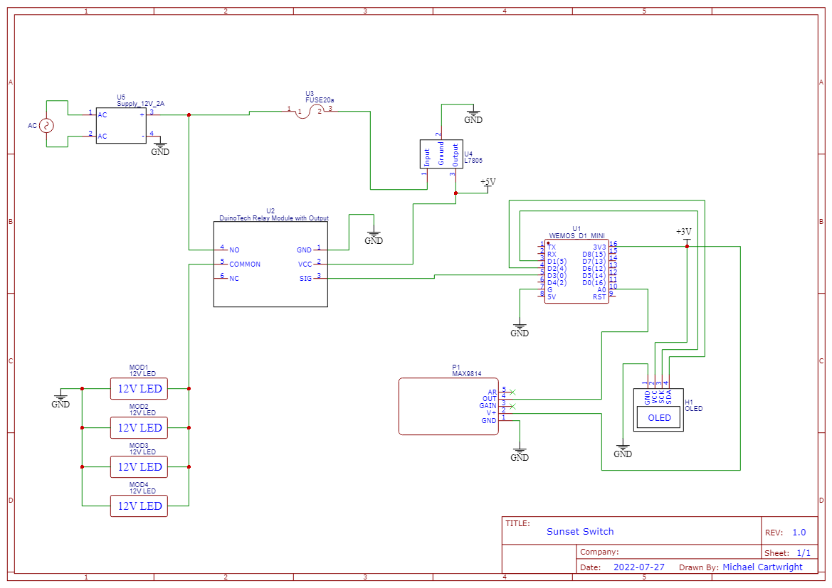
I won't give paint-by-numbers instructions. Instead, I'll just supply a full schematic and the source of my Arduino sketch along with some notes on the implementation each of the features. I suspect nobody will build this exact device but may well benefit from copying one or more of the features for some other purpose.
Web InterfaceI take advantage of the built-in Wifi and web functionality of the D1 mini. I've used both the server and the client parts in other projects so I already had code to get past most of the common gotchas. I leave the serial output in the live version so I can easily hook up a USB cable and diagnose initialization when it fails in future.
The image below is a screenshot showing what my simple web user interface looks like:
I use ESP8266WebServer for the web server and this documentation is actually pretty good. My use of a <button> tag and a <meta> refresh is a quick and dirty way of gettings some web buttons to work.
The only reason to have an OLED display on the device is so that we can easily know which IP address has been allocated to it so we can actually find the web server in the browser. But, once you've got a display, you may as well include other diagnostic information: I just replicated the same stuff as the web UI:
However, OLED displays do burn out over time (~4-5 years) so it makes sense not to leave them "always on". For this reason I used a microphone sensor as a switch to turn the OLED on for 15 seconds. The enclosure makes for a convenient sound box so you can simply tap on the box with a knuckle to turn on the OLED. I have a project about using the MAX9814 as an Audio Switch that describes this trick in more detail.
Originally I thought I could simply switch the 12V supply using a MOSFET switch like the VO12642T since it can handle 2A and isolates this current from the delicate electronics. However, after measuring the current draw of the exterior LED lights at 1.7A it made me change to something with more capacity to not be that close to the 2A limit. I had a 10A relay breakout board on hand so I used that instead.
Add a 7805 regulator to get us a 5V supply from the 12V LED driver and that's pretty much the circuit done. I added a 1A fuse for the delicate electronics (because I'm getting older and wiser). Another important thing to remember is that not all the delicate stuff is 5V: both the OLED and the MAX9814 have 3.3V logic levels and are small enough to be powered using the 3.3V supply from the D1 mini.
I keep time using Arduino millis() which is not known to be terribly accurate and will wrap around every ~50 days. My solution is to reset the time once every 24 hours using worldtimeapi.org, a free public web service.The API for me, being in New Zealand, is:http://worldtimeapi.org/api/timezone/pacific/auckland
Note:http://, not https://
I use a second free public web service to get today's sunset time at my location (yes, I could just do the math, but I'm lazy and I'm already hitting the web). At the same time I call to update the time, I also call sunrise-sunset.org to get today's sunset time for my location. Use Google maps to get your longitude and latitude. The API call will be something like:http://api.sunrise-sunset.org/json?lat=-YY.YYYY&lng=XX.XXXX
Note:http://, not https://
These web service calls are made using the reliable WiFiClient and this documentation is pretty good.
Both of these web services return the response as JSON. I've found that this JSON library is great for parsing these responses.
So, as a reminder, three things you need to customize in my code according to your details:
STASSIDandSTAPSK- ssid and password for your own home WiFi- The URL for the web call to
worldtimeapi.orgbased on your time zone - The URL for the web call to
sunrise-sunset.orgbased on your location
Screenshots from Arduino IDE 2.x just in case you get stuck trying to find the correct drivers:
This last one is probably what you'd install anyway to use the Wemos LOLIN D1 mini and I believe that includes the web server and client libraries.
AssemblyI'm installing the microcontroller circuitry inside the same enclosure that houses the AC mains to 12V DC power supply for the LED lights. I've made the mistake on previous projects of making things too tight and too small. I've also made the mistake of making things too hard to disassemble and take out of the field and back to the workbench.
Using a cutting blade of my Dremel made it easy to take a 4mm thick sheet of "craft" plywood and get it perfectly sized for a squeeze fit: sits snuggly in the enclosure but can still be easily removed.
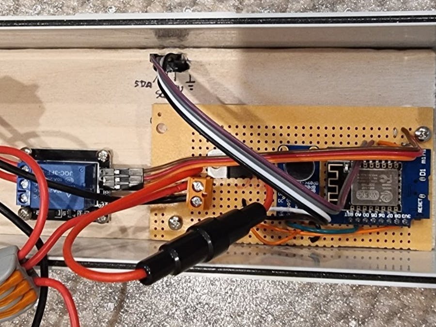
Major components are screwed to the plywood. The USB port on the microcontroller is still accessible. The 3 connections to the 12V power and the LEDs are easily disconnected and reconnected.
EpilogueMy "philosophy" mentioned at the start is aspirational: the design needs to evolve into this ideal state.
So, when I discover what's wrong with this system in future, I will fix it and update this project. Stuff just needs to work reliably.


Comments
Please log in or sign up to comment.