Hardware components | ||||||
| × | 1 | ||||
_wzec989qrF.jpg?auto=compress%2Cformat&w=48&h=48&fit=fill&bg=ffffff) |
| × | 1 | |||
Use Arduino to control the DC motor speed regulator MST_K12.
The benefits of interfacing MST_K12 with Arduino are:
- Software control by entering commands via the serial monitor
- Adjust the speed level with the ability to set a time profiles
- Switching on and off the motor
- Storage of the adjusted regulation level
- Remote control (not using the potentiometer)
- Ability to manage the operation time/off for particular applications
MST_K12 & Arduino
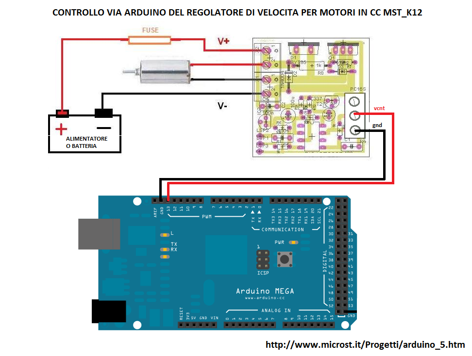
The hardware implementation is performed using the Arduino MEGA 2560 card and the MST_K12 regulator without the potenziometerreplaced by a screw connector: It is needed to connect the positive input VCNT to the pin 13 pf the arduino card and the negative input pin GND to the gnd of the card as shown in the figure.
The principle of the control is very simple: in normal operation the MST_K12 takes the voltage, set by potentiometer, to control of the regulation value. To replace the potentiometer it is needed something that can generate a variable voltage from 0 to 5V into 256 levels. There comes to the aid of the PWM Arduino that has the ability to generate a PWM signal, via command, for some pin (2-13) with a value that ranges from 0% to 100%. As described in the tutorial on the use of the PWM it is possible to generate a DC voltage by a PWM signal. The value of this voltage that call VCNT = D / 100 VDC. where D is the duty cycle in% and VCC is the maximum voltage of the PWM signal. In our case, for the Arduino, VCC = 5V that is compatible with the internal operation of the MST_K12 voltage while D may vary from 0% to 100%. For example, if you want a 50% speed regulation enough to set the duty cycle of the pin 13 to 50% because at this corresponds to a voltage VCNT = 5 * 50/100 = 2.5V which is for the MST_K12 the voltage value for 50% of control level. To switch off the controller just put the duty cycle to zero while to turn it on just put the duty cycle of the pin 13 to the previous value or a new value different from zero.
The principle of the control is very simple: in normal operation the MST_K12 takes the voltage, set by potentiometer, to control of the regulation value. To replace the potentiometer it is needed something that can generate a variable voltage from 0 to 5V into 256 levels. There comes to the aid of the PWM Arduino that has the ability to generate a PWM signal, via command, for some pin (2-13) with a value that ranges from 0% to 100%. As described in the tutorial on the use of the PWM it is possible to generate a DC voltage by a PWM signal. The value of this voltage that call VCNT = D / 100 VDC. where D is the duty cycle in% and VCC is the maximum voltage of the PWM signal. In our case, for the Arduino, VCC = 5V that is compatible with the internal operation of the MST_K12 voltage while D may vary from 0% to 100%. For example, if you want a 50% speed regulation enough to set the duty cycle of the pin 13 to 50% because at this corresponds to a voltage VCNT = 5 * 50/100 = 2.5V which is for the MST_K12 the voltage value for 50% of control level. To switch off the controller just put the duty cycle to zero while to turn it on just put the duty cycle of the pin 13 to the previous value or a new value different from zero.

MST_K12 arduino control software
ArduinoHere is the Arduino code. Using the serial interface of the Arduino IDE it is possible to control the MST_K12 regulator. The commands are sent to the Arduino card that translates them into commands for MST_K12.
The commands are:
a: turn on the controller to the speed regulation value set by rxxx command. At the first power on, the speed regulation value should have set before through rxxx command;
s: switch-off of the regulator. The speed regulation value is set to zero while the value set via the rxxx command is not lost but stored because it will be used at the next ignition;
rxxx: sets the speed regulation value: xxx is the percentage of adjustment which can vary from 0 to 100;
q: returns the status of the motor (on or off) and of the current speed regulation value;
/*CONTROL PROGRAM CONTROLLER MST_K12 WAY THROUGH SERIAL INTERFACE
Code for piloting of MST_K12 speed regulator. By connecting pin 13 at the entrance VCNT MST_K12 the positive and the negative input to GND GND of Arduino boards (MEGA), the controller may be controlled by sending commands via the serial monitor IDE dell'arduino with speed set to 9600.
The commands accepted are:

a - turn on the MOTOR
s - switch off the MOTOR
q - requests the status of the MOTOR.

    Possible answers:
    ENGINE on with speed regulation at xxx%
    ENGINE off with speed regulation at xxx%

rxxx - set the speed regulation value at the xxx%. possible values for "xxx" are from 0 to 100. Spaces are ignored.
The accepted characters are only numbers (0 through 9).
*/

//pin
const byte vcnt = 13; //output pwm

//variabili globali
byte regolazione = 0;  // contains the % value of the pwm on pin 13
int start =0;          // enable ignition of the regulator
void setup() {
  pinMode(vcnt,OUTPUT);
  analogWrite(vcnt, regolazione);
  Serial.begin(9600); // set the serial interface
  delay(1000); // wait a 1s
  Serial.println(F("Serial Interface ready ")); //are ready
  Serial.println(F(" a= turn on; s= turn off; rxxx = set regulation at  xxx%; q= motor status"));

}

//main program
void loop() {
  int lettura; // PWM value read from serial
  unsigned long tempMillis; // set rx  timeout
  byte caratteri; // rx char number
  byte tempChar; // read char

  // check if a byte is received
  if (Serial.available()) {
    byte command = Serial.read(); //read the first bye
    switch (command) { // check if it is valid
      case 'a': // turn on the MOTOR
        //;regolazione = 100;
        start =1;
        analogWrite(vcnt, start*regolazione*255/100);
        Serial.print(F("MOTOR"));
        Serial.print(F(" is on with regulation at "));
        Serial.print(regolazione, DEC);
        Serial.println("%");
        break;
      case 's': // turn off the MOTOR
        start=0;
        analogWrite(vcnt, 0);
        Serial.println(F("MOTOR off"));
        break;
      case 'q': // user wants to know the MOTORE status
        Serial.print(F("MOTOR "));
        if (start == 0) {
          Serial.print(F("off"));
        } else if (start == 1) {
          Serial.print(F("on"));
        }
          Serial.print(F(" regulation at "));
          Serial.print(regolazione, DEC);
          Serial.println("%");

        break;
      case 'r': // set pwm
        lettura = 0;
        tempMillis = millis();
        caratteri = 0;
        // I need other chars
        do {
          if (Serial.available()) {
            tempChar = Serial.read();
            caratteri++;
            if ((tempChar >= 48) && (tempChar <= 57)) { //is it a number? ok
              lettura = (lettura * 10) + (tempChar - 48);
            } else if ((tempChar == 10) || (tempChar == 13)) {
              //
              break;
            }
          }
          //abort for timeout, for pwm value > 255
          //or for more un-significant chars
        } while ((millis() - tempMillis < 500) && (lettura <= 100) && (caratteri < 10));
        // if pwm value is valid, the set the pin pwm
        if (lettura <= 100) {
          regolazione = lettura;
          analogWrite(vcnt, start*regolazione*255/100);
          Serial.print(F("regulation set at "));
          Serial.print(regolazione, DEC);
          Serial.println("%");
         }
        break;
    }
    // clear the buffer
    while (Serial.available()) {
      byte a = Serial.read();
    }
  }
}


Comments
Please log in or sign up to comment.