


Hardware components | ||||||
 |
| × | 1 | |||
 |
| × | 1 | |||
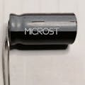
The MST_K800 project is a speedometer or tachometer for electric motors equipped with a magnetic tachometer sensor like the one mounted in most washing machine motors (with or without brushes). The speedometer shows on the LCD display (16 X2) the number of instantaneous and average revolutions of the motor shaft in RPM (revolutions per minute). It also displays the motor status (RUN / STOP). For its operation an external continuous power supply is required with values between 8V and 15V. The circuit connects directly to the output of the engine speed sensor. The MST_K800 speedometer adapts perfectly to all motors that can be controlled with the MST_K07_CL regulator. In the following photo, the prototype of the assembled MST_K800.
Photo of the assembled MST_K800 digital speedometer
Description of the speedometerAs mentioned in the introduction, the MST_K800 digital speedometer has been designed to be coupled to washing machine motors equipped with a tachometer sensor. This speedometer is very useful if you are using an engine speed control to get a good and accurate indication of the engine RPM. Especially suitable when using the MST_K07_CL torque controlled speed controller.
In the dig_rpm project, present on the site, two digital tachometers for washing machine motors based on Arduino Nano and visualization on a 16X2 LCD display controlled with I2C protocol have been developed. These speedometers implement two different techniques to read the number of revolutions from the sensor: reading of the amplitude (amp_mode) and frequency (freq_mode) of the signal coming out of the tachometer sensor.
The MST_K800 tachometer implements the technique of reading the frequency of the signal outgoing from the sensor. The following figure shows the block diagram of the speedometer.
As you can see, the speedometer is essentially composed of three blocks:
Processing, Conditioning, Feeding:The processing block is the main one based on an 8-bit microcontroller. This manages the processing of the signal coming from the conditioning circuit and drives the 16X2 LCD display based on the HD44780 protocol. In short, the micro implements a frequency meter as it reads the frequency of the signal coming out of the conditioning circuit. The processing consists in dividing the frequency of the signal by a factor N equal to the number of poles of which the sensor is composed. Generally the number of poles is 8. The divided signal is measured in frequency for an interval of 2 seconds to generate the current RPM value and averaged over 4 measurement intervals to generate the AVG information shown on the display. The display also shows the motor status (RUN or STOP). If we indicate with Fin the frequency of the signal outgoing from the sensor, the formula that allows us to obtain the value of the revolutions expressed in RPM is:
RPM = (Fin / N) * 60
for N = 8 the formula becomes:
RPM = (Fin / 8) * 60
So, for example, a frequency Fin = 2kHz (maximum allowed input) corresponds to a rotation speed of 15000 RPM.
The conditioning block is a circuit that has the task of squaring the sinusoidal signal coming from the sensor and making it compatible with the input of the micro that reads it. It is based on a transistor and is the PCB version of the conditioning circuit for the dig_rpm project freq_mode version.
The power supply block is used to generate the internal operating voltage of the K800 by lowering the input voltage to the adjusted value of 5V. This voltage powers the microcontroller, the display and the display backligth LED. The power supply voltage is also present on pin 1 of the 4-pole AUX connector (usable for interfacing with the MST_K07_CL).
The following table shows the main electrical characteristics of the digital MST_K800 speedometer.
The frequency Fin is that of the signal coming out of the sensor. The maximum value of this corresponds to a rotation speed of 15000 RPM
Installing the digital speedometerThe installation of the digital speedometer includes the electrical connection to the power supply and to the engine speedometer sensor. The speedometer consists of two parts: the main board and the LCD display. The connection between the two parts takes place via a 16-position multipole connector. The male part of the connector is soldered on the main board while the female connector in the display circuit. In the following photos the main board and the back of the complete speedometer showing the connection between the two parts (DISPLAY + main board).
Figure 3: photo of the main board and back of the MST_K800 - detail of the connection with the display.
Electrical connectionsThe electrical connections of the digital speedometer must be made according to the diagram in figure 4 taking into account the function of the individual connectors as described in the following table.
Electrical connections diagram of the MST_K800
The speedometer power supply must be of the continuous type with values between 8 and 15Vdc with a minimum deliverable current of 100mA. The circuit is protected against reverse polarity of the power supply.
Regarding the connection to the sensor, no polarity must be respected as the signal coming out of the sensor is of the sinusoidal type.
AUX connectorThe 4-pin connector on the MST_K800 PCB allows the electrical connection of the speedometer with external circuits. The table shows the mapping of the AUX connector.
AUX connector mapping
The 5V line (pin 1) and the GND (pin 2) allow to power the external circuits that interface with the speedometer. This power supply line can also be used to power the tachometer from the outside through a regulated voltage of 5V. In this case, do not connect any voltage to the main power connector, leaving it free. You can think of using a smartphone charger as a 5V voltage source.
The IN input, on the other hand, can be used as an alternative circuit input by bypassing the conditioning circuit. The signal that can be applied to the IN input must be a 5V digital signal or from an open drain as the IN line has a resistive pull-up towards 5V. In this case, the main input must be deactivated by putting a short between the inputs.
The READY signal is a signal that indicates that the speedometer is ready. This is to give consent to external circuits to be able to leave. For the time in which the speedometer is in the ignition phase this signal is set to gnd while when the speedometer is ready this line is left free (float).
Standard connection of the MST_K800Figure 5 shows the standard connection of the speedometer to the sensor and to the power supply supplied by an external power supply (connected to the mains).
typical connection of the MST_K800
Connections MST_K800 and MST_K07_CLThe MST_K800 circuit has been designed to be coupled to the MST_K07_CL regulator. In this case the speedometer must be connected as in figure 6:
Connection between MST_K800 and MST_K07_CL
The sensor signal input must be taken from the sensor input terminal block of the controller while the speedometer power supply is supplied by an external power supply. If you want you can switch (optional connection), via the AUX connector of the speedometer, the power supply to the regulator using the AUX connector of the regulator. In this case the controller would go into forced feed mode. If the speedometer (and therefore also the regulator) is powered from the AUX connector, the connections are as in figure 7:
connection between MST_K800 and MST_K07_CL with external power supply from the AUX connector
VideoBelow is the video made to show the operation of the speedometer together with the MST_K07_CL regulator and an MCA3064 washing machine motor:

Comments
Please log in or sign up to comment.