

Hardware components | ||||||
 |
| × | 1 | |||
 |
| × | 1 | |||
| × | 1 | ||||
 |
| × | 1 | |||
Software apps and online services | ||||||
 |
| |||||
_4YUDWziWQ8.png?auto=compress%2Cformat&w=48&h=48&fit=fill&bg=ffffff) |
| |||||
Some of you may be familiar with this project from my previous article earlier this year. Basically, I dug up the remains of my old, broken, and abandoned Fluke 87V to give it a new purpose: waking me up in the morning. Since publishing that article, I have been using the device as my alarm clock every day and slowly adding upgrades. This article will provide a quick recap on some of the features I have added since January!
Programming AdapterOne of the more annoying things about my original design was the requirement of partially disassembling the meter to get access to the UART header for programming. This not only makes it inconvenient for adding new software features over time but also places a good amount of stress on the 87V enclosure when having to peel apart the clamshell every time a bug fix is needed.
In the original article, I initially addressed this by routing DuPont wires out of one of the input banana jack holes to connect my FTDI cable. While this does definitely add to the whole "hacked" aesthetic, it does kind of ruin the original looks of the Fluke 87V. So, in order to not sacrifice the very important *styling*, I decided to glue the original banana jack assembly to the enclosure and solder the UART programming wires (TX, RX, DTR, GND) to the banana jacks!
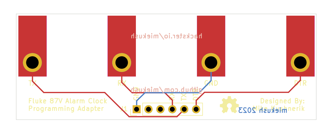
This worked great and I could now easily program the ATMEGA328P without any disassembly. But, I of course had to go the extra mile and design a quick adapter PCB so I wouldn't have fiddle around with cables and remember which pin is wired to each jack.
Segment Decoding 2: Electric BoogalooIn the original article I decoded some of the display segments through trial and error just to get the seven segment display working. Though, if I wanted to add new features I figured it would be a good idea to put in the effort to actually decode all the display segments.
After some brainstorming I decided on the method of writing a simple program that sequentially turns on every segment in the display ram and prints out the address to the serial terminal.
#include "bu9796.h"
#define BKLT_PIN        3
BU9796 display;

void setup()
{
  Serial.begin(115200);
  Serial.println("Starting segment test...");

  pinMode(BKLT_PIN, OUTPUT);
  digitalWrite(BKLT_PIN, HIGH);

  display.begin();
}

void loop()
{
  display.clearBuffer();

  for(int i=0; i<10; i++)
  {
    for(int j=0; j<8; j++)
    {
      Serial.print("Byte:");
      Serial.print(i);
      Serial.print(" Bit:");
      Serial.println(j);

      display.setSegment(i, 1<<j);
      display.update();
      delay(1000);
    }
  }
}
With the program running, all I need to do is record a video with the terminal output and Fluke 87V screen in the same frame and I can then go through the video frame by frame and (manually) decode which segment in the BU9796 ram actually corresponds to each segment in the Fluke 87V display.
While this was a super monotonous process, I'm glad I actually took the time to knock this out as it really helped with the rest of the features I added later. To make it easy for controlling individual display segments using this map I also added a setSegment function that takes in a BU9796 RAM byte number and a bit mask and sets the corresponding bit in the display buffer.
Alarm Setting (without reprogramming)Easily the most annoying thing about my original design was the lack of an in-meter configuration for the wake up alarm time. This meant every time I wanted to change my alarm setting I would need to change the alarm time variable in my Arduino program and flash the new sketch to the device. While I did just make programming the device a lot easier, I decided this feature was definitely a must have.
To start, I realized I would likely need some additional buttons for entering the alarm setting and adjusting the alarm time so I upgraded my existing (simple) button polling function to add the remaining meter buttons and a button counter that tracks the button press duration for detection of short and long presses.
After I had my updated button polling function prepared, I then decided on how I wanted the alarm setting to behave. After some deliberation, I ended up deciding on using the continuity buzzer button for enabling the alarm and the HOLD symbol for indicating the alarm status on the display. Some of you may be wondering why I didn't just use the continuity buzzer symbol for this but, unfortunately, I didn't connect this segment to the BU9796. It's okay, HOLD will do just fine.
I won't go into much detail to explain the rest of the alarm settings mode since I think the gif above captures it pretty well but essentially the user enables the alarm by short pressing the continuity buzzer button. Once enabled, the user can enter the alarm settings mode by long pressing (press > 1500ms) the same switch. In alarm settings mode, the current alarm time is blinking on the display (thanks BU9796!) and the user can press the RANGE switch to increment the alarm time or the REL switch to decrement the alarm time in 30 minute intervals. Pressing the continuity buzzer button will set the alarm time variable then store the alarm time value in the ATMEGA328P EEPROM and return to the normal clock mode.
Bar Graph Seconds DisplayAfter spending a bunch of time decoding all the Fluke 87V display segments earlier, I decided to implement something I was considering for the original project but never got to: seconds display.
While the Fluke 87V display doesn't have enough digits to display the actual seconds in decimal form, I had the idea instead to use the bar graph at the bottom of the display for showing a rough, digital representation. I'll again skip most of the boring implementation details but I basically created another array (bar_graph_map) that stores the RAM byte/bit for each bar graph segment in sequential order and added a simple function that takes in a value from 0->30 and then sets the corresponding number of segment digits on the display. I then call this function when I update the clock time and pass in the RTC seconds divided by two since there are only 30 bar graph segments (technically there's 32 but I just used 30).
RTC Calibration over UARTAnother thing that was really annoying about the original project was the RTC date/time setting process. This isn't really unique to my project since pretty much all projects with an RTC peripheral and no direct method of synchronization with an external clock (i.e. Wi-Fi, GPS, etc...) require you to set the RTC using either an explicit datetime object defined in your program or using the compile time of the program, usually with some offset to compensate for the programming time.
Though, you might be thinking this isn't such a big problem considering this is like a one time thing, right? In an ideal world, maybe. But, (unfortunately) we live in a world where people use TX and RX for defining serial interfaces and have real time clock sources that slowly drift over time. This means the time we set in our RTC today may drift by seconds or even minutes each year!
To determine how much your clock will drift, you can use this handy calculator provided by Analog Devices. All you need to do is confirm the parts per million (ppm) deviation of your RTC's clock source (i.e. crystal) and then use it to calculate the actual frequency error of your oscillator and the resulting clock drift. Also, if you plan to use your device in harsh thermal environments you should also consider the temperature dependent frequency error.
For example, an RTC using a 10ppm clock source will drift roughly 0.86 seconds/day or 5.26 minutes/year at 25° C!
The clock source used in the Fluke 87V clock's RTC (DS3231) actually has pretty good accuracy (2ppm from 0-40° C) and is temperature compensated to ensure a stable clock frequency across a wide temperature range (3.5ppm from -40-85° C).
Though, even with the small drift of roughly 1 minute/year with the DS3231, I figured it would be still valuable to design an easier method for synchronizing the RTC.
After some brainstorming, I came up with the idea of adding an RTC calibration mode in the Meter and then preparing an application that runs on a PC to send the latest time over UART which can then be used to the set the RTC. Taking advantage of the programming adapter I made earlier, this should make it super easy to calibrate the RTC every once and a while using any Windows laptop/PC.
To enter the RTC calibration mode, I thought it might be cool to make another homage to the original Fluke 87V software and mirror it's calibration mode which can be entered by holding down the MIN MAX button while turning on the Meter. The letters "CAL" are displayed on the screen to indicate you have entered the calibration mode correctly.
To mirror this, I simply added a statement to check the status of the MIN MAX switch in setup and, if pressed, enter the calibration mode, print "CAL" to the display, and wait for the datetime data over UART from the PC. Whenever a string arrives from the PC (format: YYYYMMDDHHMMSSWWyyy\n), the individual datetime signals are extracted and the RTC is adjusted. As a little feedback to the user I also added a backlight flash whenever a datetime string arrives.
For the PC side, I prepared a quick python script that uses the time module to get the latest PC time and sends it over UART to the Fluke 87V clock every second.
import serial
import time

fluke87v = serial.Serial(port='COM28', baudrate=9600, timeout=.1)

prev_second = -1;

while True:
    current_time = time.localtime()

    if(current_time.tm_sec != prev_second):
        message = bytes(str(f"{current_time.tm_year:04d}")+
                        str(f"{current_time.tm_mon:02d}")+
                        str(f"{current_time.tm_mday:02d}")+
                        str(f"{current_time.tm_hour:02d}")+
                        str(f"{current_time.tm_min:02d}")+
                        str(f"{current_time.tm_sec:02d}")+
                        str(f"{current_time.tm_wday:02d}") +
                        str(f"{current_time.tm_yday:03d}") + "\n", 'utf-8')
        print(message);
        fluke87v.write(message)
prev_second = current_time.tm_sec;Outside of a bunch of miscellaneous bug fixes this is pretty much all the updates I have made to the Fluke 87V clock over the course of the last 8 or so months. As of right now I'm pretty satisfied with the overall feature set of the device, but I'm sure there is still room for improvement and I may come back to this project again to add more upgrades in the future.
I hope this status update was an interesting read and please let me know if you have any feedback for my future project writeups!


_Ujn5WoVOOu.png?auto=compress%2Cformat&w=40&h=40&fit=fillmax&bg=fff&dpr=2)


Comments
Please log in or sign up to comment.