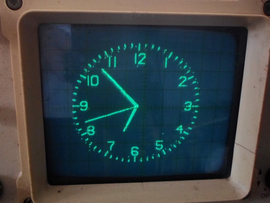
This is the simplest way to generate an analog clock on the oscilloscope display. The oscilloscope should be two-channel, one channel for the "x" axis and the other for "y". On the GitHub page of Mauro Pintus, there is a detailed description and code that use internal DACs of ESP32 microcontroller and WiFi ntp clock sync.By default this sketch will start from a fix time 10:08:37 everityme you reset the board.
To change it, modify the variables h, m, s below. To synchronize the clock with an NTP server, you have to install the library NTPtimeESP from Andreas Spiess. Then ncomment the line //#define NTP, removing the //. Edit the WiFi credential in place of Your SSID and Your PASS. Check in the serial monitor if it can reach the NTP server.
The NTPtimeESP library was meant for the ESP8266 and you need to adit the file NTPtimeESP.h to use it with the ESP32. Open up the "NTPtimeESP.h" inside the library and replace the "#include <ESP8266WiFi.h>" with "#include <WiFi.h>".
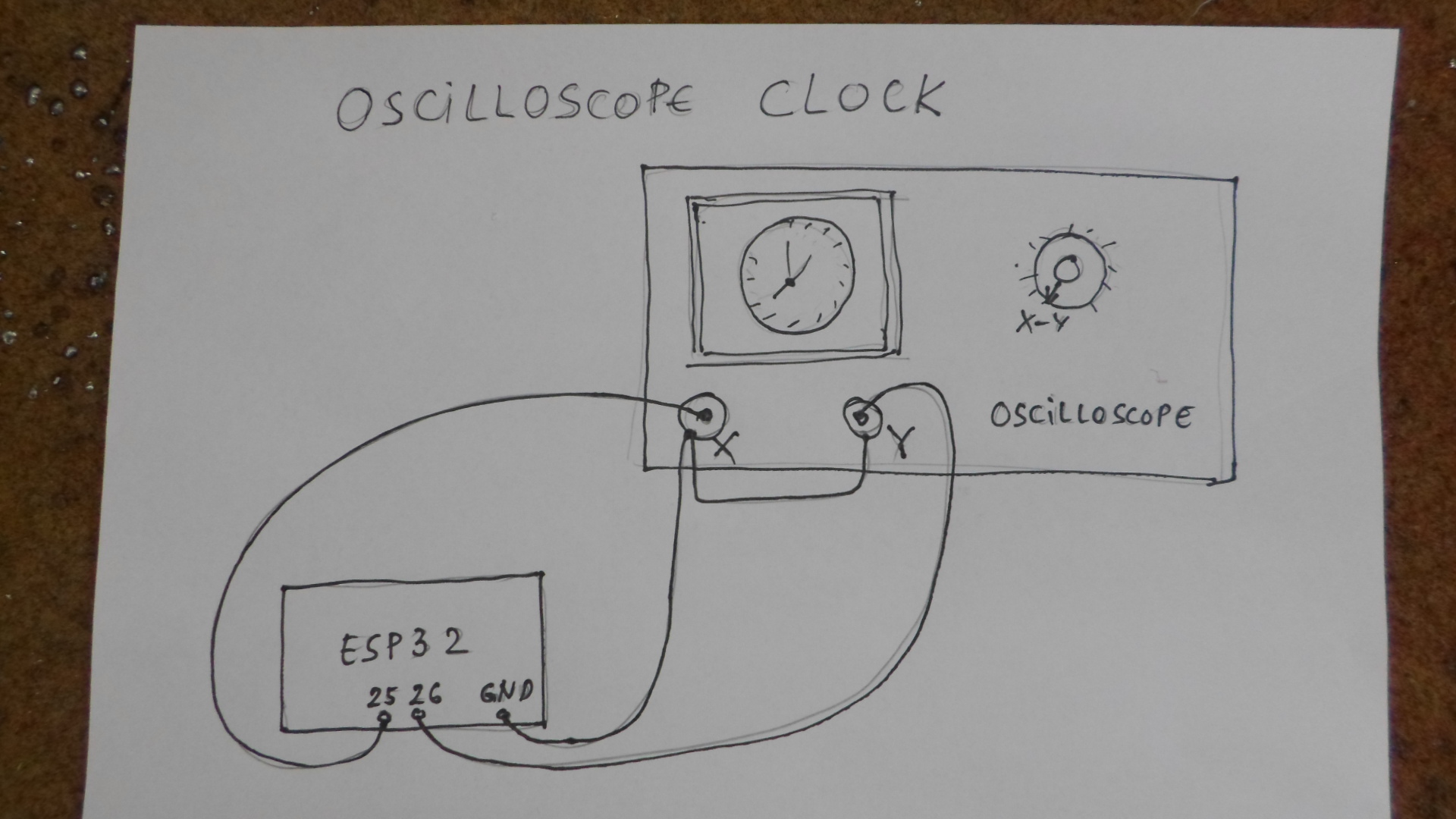
As you can see on the circuit, pin 25 of ESP32 is connected to "x" (channel 1) of oscilloscope, and pin 26 to "y" (channel 2). Then we select a X-Y mode of operation of the oscilloscope. Connecting is done with shielded cables. On the video you can see flickering in the image, which is a consequence of the outdated oscilloscope.


Comments
Please log in or sign up to comment.