


Hardware components | ||||||
 |
| × | 1 | |||
| × | 1 | ||||
 |
| × | 1 | |||
| × | 1 | ||||
 |
| × | 1 | |||
 |
| × | 1 | |||
Software apps and online services | ||||||
 |
| |||||
Hand tools and fabrication machines | ||||||
 |
| |||||
This is an LCD clock made with DS3231 real-time clock module, which unlike DS1307 has the possibility of alarm and temperature monitor. In this case, the LCD screen displays the date, time, two alarms and also the current temperature. And the most interesting part is that the complete settings of the clock as well as muting the alarm is done through the TV remote controller.
Hardware parts required for building:
-Arduino board
-DS3231 RTC board
-20X4 LCD display
-I2C Arduino LCD Display Module
-RC5 protocol IR remote control
-IR receiver
-LED
-Buzzer
-220 Ohm resistor
The basic code is taken from simple-circuit web page And I made a few changes : For simplicity, I added an I2C module to the LCD display and modified the code accordingly. I also added a small buzzer that generates sound with a given frequency while the alarm is active.
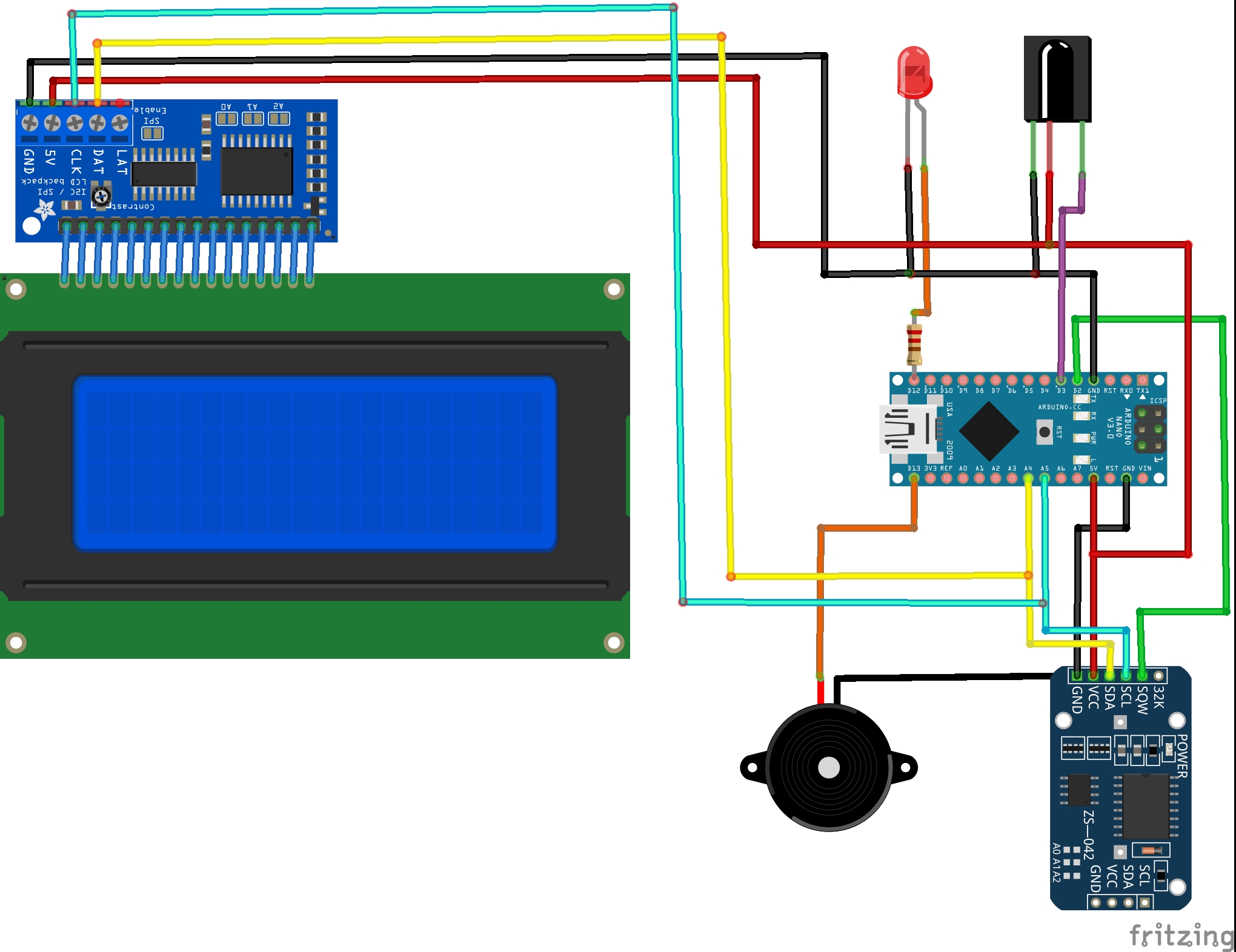
The DS3231 board is supplied with 5V as the 20x4 LCD and the IR receiver, this 5V comes from the Arduino board, there are 3 data lined connected between this board and the Arduino, SCL line is connected to analog pin 5, SDA is connected to analog pin 4 and INT line is connected to digital pin 2 which is the external interrupt pin of the Arduino (INT0). The DS3231 interrupts the microcontroller when there is an alarm (alarm1 or alarm2).
The IR receiver has 3 pins: GND, VCC and OUT where the OUT pin is connected to Arduino pin 3 which is external interrupt pin (INT1).
The LED which is connected to Arduino pin 12 is used as an alarm indicator (alarm1 or alarm2), so if there is an alarm the DS3231 pulls down the INT pin which interrupts the microcontroller (ATmega328P) and the microcontroller turns the LED ON, here a button on the remote control turns both the LED and the occurred alarm OFF.
We need to decode our remote control in order to know the code of each button because we’ve to add it in the Arduino software (code).
The remote control used in this project is a TV IR remote control with RC5 protocol, it’s the one shown below (used buttons are numbered):
Button Function Code (hex format)
1 Increment 0x20
2 Set time and calendar 0x10
3 Decrement 0x21
4 Set alarms 0x11
5 Reset alarms 0x0C
Note that this code must use the remote control with the RC5 protocol, and most often such remote devices are used by older Philips devices. Below is a simple code "IR protocol finder" that allows you to easily determine the protocol of any remote control, as well as the value of each button.
The picture shows the remote control I used with the marked values and functions of the buttons.
/* Arduino real time clock and calendar with 2 alarm functions, temperature monitor and RC-5 IR remote control
Read DS3231 RTC datasheet to understand the code
DS3231 interrupt pin is connected to Arduino external interrupt pin (pin #2).
*/
// Define number of Timer1 ticks (with a prescaler of 1/8)
#define short_time 1400 // Used as a minimum time for short pulse or short space ( ==> 700 us)
#define med_time 2400 // Used as a maximum time for short pulse or short space ( ==> 1200 us)
#define long_time 4000 // Used as a maximum time for long pulse or long space ( ==> 2000 us)
// include LCD library code
#include <LiquidCrystal_I2C.h>
// include Wire library code (needed for I2C protocol devices)
#include <Wire.h>
LiquidCrystal_I2C lcd = LiquidCrystal_I2C(0x27, 20, 4);
const int alarm_pin = 12; // Alarms pin number
const int buzzer = 13;
void setup() {
pinMode(alarm_pin, OUTPUT);
pinMode(buzzer, OUTPUT);
digitalWrite(alarm_pin, LOW);
lcd.begin();
lcd.backlight();
// Timer1 module configuration
TCCR1A = 0;
TCCR1B = 0; // Disable Timer1 module
TCNT1 = 0; // Set Timer1 preload value to 0 (reset)
TIMSK1 = 1; // enable Timer1 overflow interrupt
Wire.begin(); // Join i2c bus
attachInterrupt(1, RC5_read, CHANGE); // Enable external interrupt (INT1)
attachInterrupt(0, Alarm, FALLING); // Enable external interrupt (INT0)
}
// RC5 remote control variables
boolean rc5_ok = 0, toggle, last_toggle;
byte rc5_state = 0, j;
unsigned int rc5_code;
// RTC Variables declaration
bool alarm1_status, alarm2_status;
char Time[] = " : : ",
calendar[] = " / /20 ",
alarm1[] = "A1: : :00", alarm2[] = "A2: : :00",
temperature[] = "T: . C";
byte i, second, minute, hour, day, date, month, year,
alarm1_minute, alarm1_hour, alarm2_minute, alarm2_hour,
status_reg;
void RC5_read() {
unsigned int timer_value;
if(rc5_state != 0){
timer_value = TCNT1; // Store Timer1 value
TCNT1 = 0; // Reset Timer1
}
switch(rc5_state){
case 0 : // Start receiving IR data (initially we're at the beginning of mid1)
TCNT1 = 0; // Reset Timer1
TCCR1B = 2; // Enable Timer1 module with 1/8 prescaler ( 2 ticks every 1 us)
rc5_state = 1; // Next state: end of mid1
j = 0;
return;
case 1 : // End of mid1 ==> check if we're at the beginning of start1 or mid0
if((timer_value > long_time) || (timer_value < short_time)){ // Invalid interval ==> stop decoding and reset
rc5_state = 0; // Reset decoding process
TCCR1B = 0; // Disable Timer1 module
return;
}
bitSet(rc5_code, 13 - j);
j++;
if(j > 13){ // If all bits are received
rc5_ok = 1; // Decoding process is OK
toggle = bitRead(rc5_code, 11); // Toggle bit is bit number 11
rc5_code &= 0x07FF; // Remove the two start bits and the toggle bit from the code message
detachInterrupt(1); // Disable external interrupt (INT1)
return;
}
if(timer_value > med_time){ // We're at the beginning of mid0
rc5_state = 2; // Next state: end of mid0
if(j == 13){ // If we're at the LSB bit
rc5_ok = 1; // Decoding process is OK
bitClear(rc5_code, 0); // Clear the LSB bit
toggle = bitRead(rc5_code, 11); // Toggle bit is bit number 11
rc5_code &= 0x07FF;
detachInterrupt(1); // Disable external interrupt (INT1)
return;
}
}
else // We're at the beginning of start1
rc5_state = 3; // Next state: end of start1
return;
case 2 : // End of mid0 ==> check if we're at the beginning of start0 or mid1
if((timer_value > long_time) || (timer_value < short_time)){
rc5_state = 0; // Reset decoding process
TCCR1B = 0; // Disable Timer1 module
return;
}
bitClear(rc5_code, 13 - j);
j++;
if(timer_value > med_time) // We're at the beginning of mid1
rc5_state = 1; // Next state: end of mid1
else // We're at the beginning of start0
rc5_state = 4; // Next state: end of start0
return;
case 3 : // End of start1 ==> check if we're at the beginning of mid1
if((timer_value > med_time) || (timer_value < short_time)){ // Time interval invalid ==> stop decoding
TCCR1B = 0; // Disable Timer1 module
rc5_state = 0; // Reset decoding process
return;
}
else // We're at the beginning of mid1
rc5_state = 1; // Next state: end of mid1
return;
case 4 : // End of start0 ==> check if we're at the beginning of mid0
if((timer_value > med_time) || (timer_value < short_time)){ // Time interval invalid ==> stop decoding
TCCR1B = 0; // Disable Timer1 module
rc5_state = 0; // Reset decoding process
return;
}
else // We're at the beginning of mid0
rc5_state = 2; // Next state: end of mid0
if(j == 13){ // If we're at the LSB bit
rc5_ok = 1; // Decoding process is OK
bitClear(rc5_code, 0); // Clear the LSB bit
toggle = bitRead(rc5_code, 11); // Toggle bit is bit number 11
rc5_code &= 0x07FF;
detachInterrupt(1); // Disable external interrupt (INT1)
}
}
}
ISR(TIMER1_OVF_vect) { // Timer1 interrupt service routine (ISR)
rc5_state = 0; // Reset decoding process
TCCR1B = 0; // Disable Timer1 module
}
void Alarm(){
digitalWrite(alarm_pin, HIGH);
tone(buzzer, 1000);
}
void DS3231_read(){ // Function to read time & calendar data
Wire.beginTransmission(0x68); // Start I2C protocol with DS3231 address
Wire.write(0); // Send register address
Wire.endTransmission(false); // I2C restart
Wire.requestFrom(0x68, 7); // Request 7 bytes from DS3231 and release I2C bus at end of reading
second = Wire.read(); // Read seconds from register 0
minute = Wire.read(); // Read minuts from register 1
hour = Wire.read(); // Read hour from register 2
day = Wire.read(); // Read day from register 3
date = Wire.read(); // Read date from register 4
month = Wire.read(); // Read month from register 5
year = Wire.read(); // Read year from register 6
}
void alarms_read_display(){ // Function to read and display alarm1, alarm2 and temperature data
byte control_reg, temperature_lsb;
char temperature_msb;
Wire.beginTransmission(0x68); // Start I2C protocol with DS3231 address
Wire.write(0x08); // Send register address
Wire.endTransmission(false); // I2C restart
Wire.requestFrom(0x68, 11); // Request 11 bytes from DS3231 and release I2C bus at end of reading
alarm1_minute = Wire.read(); // Read alarm1 minutes
alarm1_hour = Wire.read(); // Read alarm1 hours
Wire.read(); // Skip alarm1 day/date register
alarm2_minute = Wire.read(); // Read alarm2 minutes
alarm2_hour = Wire.read(); // Read alarm2 hours
Wire.read(); // Skip alarm2 day/date register
control_reg = Wire.read(); // Read the DS3231 control register
status_reg = Wire.read(); // Read the DS3231 status register
Wire.read(); // Skip aging offset register
temperature_msb = Wire.read(); // Read temperature MSB
temperature_lsb = Wire.read(); // Read temperature LSB
// Convert BCD to decimal
alarm1_minute = (alarm1_minute >> 4) * 10 + (alarm1_minute & 0x0F);
alarm1_hour = (alarm1_hour >> 4) * 10 + (alarm1_hour & 0x0F);
alarm2_minute = (alarm2_minute >> 4) * 10 + (alarm2_minute & 0x0F);
alarm2_hour = (alarm2_hour >> 4) * 10 + (alarm2_hour & 0x0F);
// End conversion
alarm1[8] = alarm1_minute % 10 + 48;
alarm1[7] = alarm1_minute / 10 + 48;
alarm1[5] = alarm1_hour % 10 + 48;
alarm1[4] = alarm1_hour / 10 + 48;
alarm2[8] = alarm2_minute % 10 + 48;
alarm2[7] = alarm2_minute / 10 + 48;
alarm2[5] = alarm2_hour % 10 + 48;
alarm2[4] = alarm2_hour / 10 + 48;
alarm1_status = bitRead(control_reg, 0); // Read alarm1 interrupt enable bit (A1IE) from DS3231 control register
alarm2_status = bitRead(control_reg, 1); // Read alarm2 interrupt enable bit (A2IE) from DS3231 control register
if(temperature_msb < 0){
temperature_msb = abs(temperature_msb);
temperature[2] = '-';
}
else
temperature[2] = ' ';
temperature_lsb >>= 6;
temperature[4] = temperature_msb % 10 + 48;
temperature[3] = temperature_msb / 10 + 48;
if(temperature_lsb == 0 || temperature_lsb == 2){
temperature[7] = '0';
if(temperature_lsb == 0) temperature[6] = '0';
else temperature[6] = '5';
}
if(temperature_lsb == 1 || temperature_lsb == 3){
temperature[7] = '5';
if(temperature_lsb == 1) temperature[6] = '2';
else temperature[6] = '7';
}
temperature[8] = 223; // Put the degree symbol
lcd.setCursor(10, 0);
lcd.print(temperature); // Display temperature
lcd.setCursor(0, 2);
lcd.print(alarm1); // Display alarm1
lcd.setCursor(17, 2);
if(alarm1_status) lcd.print("ON "); // If A1IE = 1 print 'ON'
else lcd.print("OFF"); // If A1IE = 0 print 'OFF'
lcd.setCursor(0, 3);
lcd.print(alarm2); // Display alarm2
lcd.setCursor(17, 3);
if(alarm2_status) lcd.print("ON "); // If A2IE = 1 print 'ON'
else lcd.print("OFF"); // If A2IE = 0 print 'OFF'
}
void calendar_display(){ // Function to display calendar
switch(day){
case 1: strcpy(calendar, "Sun / /20 "); break;
case 2: strcpy(calendar, "Mon / /20 "); break;
case 3: strcpy(calendar, "Tue / /20 "); break;
case 4: strcpy(calendar, "Wed / /20 "); break;
case 5: strcpy(calendar, "Thu / /20 "); break;
case 6: strcpy(calendar, "Fri / /20 "); break;
case 7: strcpy(calendar, "Sat / /20 "); break;
default: strcpy(calendar, "Sat / /20 ");
}
calendar[13] = year % 10 + 48;
calendar[12] = year / 10 + 48;
calendar[8] = month % 10 + 48;
calendar[7] = month / 10 + 48;
calendar[5] = date % 10 + 48;
calendar[4] = date / 10 + 48;
lcd.setCursor(0, 1);
lcd.print(calendar); // Display calendar
}
void DS3231_display(){
// Convert BCD to decimal
second = (second >> 4) * 10 + (second & 0x0F);
minute = (minute >> 4) * 10 + (minute & 0x0F);
hour = (hour >> 4) * 10 + (hour & 0x0F);
date = (date >> 4) * 10 + (date & 0x0F);
month = (month >> 4) * 10 + (month & 0x0F);
year = (year >> 4) * 10 + (year & 0x0F);
// End conversion
Time[7] = second % 10 + 48;
Time[6] = second / 10 + 48;
Time[4] = minute % 10 + 48;
Time[3] = minute / 10 + 48;
Time[1] = hour % 10 + 48;
Time[0] = hour / 10 + 48;
calendar_display(); // Call calendar display function
lcd.setCursor(0, 0);
lcd.print(Time); // Display time
}
void Blink(){
byte k = 0;
while((!rc5_ok || (rc5_code != 0x10) && (rc5_code != 0x11) && (rc5_code != 0x20) && (rc5_code != 0x21)) && (k < 10)){
k++;
delay(25);
}
}
byte edit(byte x, byte y, byte parameter){
char text[3];
rc5_reset();
while(true){
if(rc5_ok && (rc5_code == 0x20 || rc5_code == 0x21)){ // If RC5 code received
if(rc5_code == 0x20){
parameter++;
if(((i == 0) || (i == 5)) && parameter > 23) // If hours > 23 ==> hours = 0
parameter = 0;
if(((i == 1) || (i == 6)) && parameter > 59) // If minutes > 59 ==> minutes = 0
parameter = 0;
if(i == 2 && parameter > 31) // If date > 31 ==> date = 1
parameter = 1;
if(i == 3 && parameter > 12) // If month > 12 ==> month = 1
parameter = 1;
if(i == 4 && parameter > 99) // If year > 99 ==> year = 0
parameter = 0;
if(i == 7 && parameter > 1) // For alarms ON or OFF (1: alarm ON, 0: alarm OFF)
parameter = 0;
}
if(rc5_code == 0x21){
if(((i == 0) || (i == 5)) && parameter < 1)
parameter = 24;
if(((i == 1) || (i == 6)) && parameter < 1)
parameter = 60;
if(i == 2 && parameter < 2)
parameter = 32;
if(i == 3 && parameter < 2)
parameter = 13;
if(i == 4 && parameter < 1)
parameter = 100;
if(i == 7 && parameter < 1)
parameter = 2;
parameter--;
}
lcd.setCursor(x, y);
if(i == 7){ // For alarms ON & OFF
if(parameter == 1) lcd.print("ON ");
else lcd.print("OFF");
}
else{
sprintf(text,"%02u", parameter);
lcd.print(text);
}
}
if(rc5_ok){
delay(200);
rc5_reset();
}
lcd.setCursor(x, y);
lcd.print(" "); // Print two spaces
if(i == 7) lcd.print(" "); // Print space (for alarms ON & OFF)
Blink(); // Call Blink function
lcd.setCursor(x, y);
if(i == 7){ // For alarms ON & OFF
if(parameter == 1) lcd.print("ON ");
else lcd.print("OFF");
}
else{
sprintf(text,"%02u", parameter);
lcd.print(text);
}
Blink();
if(i >= 5){
DS3231_read();
DS3231_display();
}
if(rc5_ok && last_toggle != toggle && ((rc5_code == 0x10 && i < 5) || (rc5_code == 0x11 && i >= 5))){
i++; // Increment 'i' for the next parameter
return parameter; // Return parameter value and exit
}
}
}
void rc5_reset(){
rc5_ok = 0; // Reset decoding process
rc5_state = 0;
last_toggle = toggle; // Save toggle bit
attachInterrupt(1, RC5_read, CHANGE); // Enable external interrupt (INT1)
}
void loop() {
if(rc5_ok){ // If RC5 code received
if(rc5_code == 0x10){ // If clock/calendar set button code received
i = 0;
hour = edit(0, 0, hour);
minute = edit(3, 0, minute);
rc5_reset();
while(true){
if(rc5_ok && (rc5_code == 0x20)){ // If button up button code received
day++; // Increment day
if(day > 7) day = 1;
calendar_display(); // Call display_calendar function
lcd.setCursor(0, 1);
lcd.print(calendar); // Display calendar
}
if(rc5_ok){
delay(200);
rc5_reset();
}
lcd.setCursor(0, 1);
lcd.print(" "); // Print 3 spaces
Blink();
lcd.setCursor(0, 1);
lcd.print(calendar); // Print calendar
Blink(); // Call Blink function
if(rc5_ok && last_toggle != toggle && (rc5_code == 0x10)) // If button B1 is pressed
break;
}
date = edit(4, 1, date); // Edit date
month = edit(7, 1, month); // Edit month
year = edit(12, 1, year); // Edit year
// Convert decimal to BCD
minute = ((minute / 10) << 4) + (minute % 10);
hour = ((hour / 10) << 4) + (hour % 10);
date = ((date / 10) << 4) + (date % 10);
month = ((month / 10) << 4) + (month % 10);
year = ((year / 10) << 4) + (year % 10);
// End conversion
// Write time & calendar data to DS3231 RTC
Wire.beginTransmission(0x68); // Start I2C protocol with DS3231 address
Wire.write(0); // Send register address
Wire.write(0); // Reset sesonds and start oscillator
Wire.write(minute); // Write minute
Wire.write(hour); // Write hour
Wire.write(day); // Write day
Wire.write(date); // Write date
Wire.write(month); + // Write month
Wire.write(year); // Write year
Wire.endTransmission(); // Stop transmission and release the I2C bus
}
if(rc5_code == 0x11){ // If alarm set button code received
i = 5;
alarm1_hour = edit(4, 2, alarm1_hour);
alarm1_minute = edit(7, 2, alarm1_minute);
alarm1_status = edit(17, 2, alarm1_status);
i = 5;
alarm2_hour = edit(4, 3, alarm2_hour);
alarm2_minute = edit(7, 3, alarm2_minute);
alarm2_status = edit(17, 3, alarm2_status);
alarm1_minute = ((alarm1_minute / 10) << 4) + (alarm1_minute % 10);
alarm1_hour = ((alarm1_hour / 10) << 4) + (alarm1_hour % 10);
alarm2_minute = ((alarm2_minute / 10) << 4) + (alarm2_minute % 10);
alarm2_hour = ((alarm2_hour / 10) << 4) + (alarm2_hour % 10);
// Write alarms data to DS3231
Wire.beginTransmission(0x68); // Start I2C protocol with DS3231 address
Wire.write(7); // Send register address (alarm1 seconds)
Wire.write(0); // Write 0 to alarm1 seconds
Wire.write(alarm1_minute); // Write alarm1 minutes value to DS3231
Wire.write(alarm1_hour); // Write alarm1 hours value to DS3231
Wire.write(0x80); // Alarm1 when hours, minutes, and seconds match
Wire.write(alarm2_minute); // Write alarm2 minutes value to DS3231
Wire.write(alarm2_hour); // Write alarm2 hours value to DS3231
Wire.write(0x80); // Alarm2 when hours and minutes match
Wire.write(4 | alarm1_status | (alarm2_status << 1)); // Write data to DS3231 control register (enable interrupt when alarm)
Wire.write(0); // Clear alarm flag bits
Wire.endTransmission(); // Stop transmission and release the I2C bus
}
if(rc5_code == 0x0C && digitalRead(alarm_pin)){ // If rset alarm button code is received with alarm (Reset and turn OFF the alarm)
digitalWrite(alarm_pin, LOW); // Turn OFF the alarm indicator
noTone(buzzer);
Wire.beginTransmission(0x68); // Start I2C protocol with DS3231 address
Wire.write(0x0E); // Send register address (control register)
// Write data to control register (Turn OFF the occurred alarm and keep the other as it is)
Wire.write(4 | (!bitRead(status_reg, 0) & alarm1_status) | ((!bitRead(status_reg, 1) & alarm2_status) << 1));
Wire.write(0); // Clear alarm flag bits
Wire.endTransmission(); // Stop transmission and release the I2C bus
}
rc5_reset();
}
DS3231_read(); // Read time and calendar parameters from DS3231 RTC
alarms_read_display(); // Read and display alarms parameters
DS3231_display(); // Display time & calendar
delay(50); // Wait 50ms
}
// End of code
#include <IRremote.h>

const int RECV_PIN = 3;
IRrecv irrecv(RECV_PIN);
decode_results results;

void setup(){
  Serial.begin(9600);
  irrecv.enableIRIn();
  irrecv.blink13(true);
}

void loop(){
  if (irrecv.decode(&results)){
        Serial.println(results.value, HEX);
        switch (results.decode_type){
            case NEC: Serial.println("NEC"); break ;
            case SONY: Serial.println("SONY"); break ;
            case RC5: Serial.println("RC5"); break ;
            case RC6: Serial.println("RC6"); break ;
            case DISH: Serial.println("DISH"); break ;
            case SHARP: Serial.println("SHARP"); break ;
            case JVC: Serial.println("JVC"); break ;
            case SANYO: Serial.println("SANYO"); break ;
            case MITSUBISHI: Serial.println("MITSUBISHI"); break ;
            case SAMSUNG: Serial.println("SAMSUNG"); break ;
            case LG: Serial.println("LG"); break ;
            case WHYNTER: Serial.println("WHYNTER"); break ;
            case AIWA_RC_T501: Serial.println("AIWA_RC_T501"); break ;
            case PANASONIC: Serial.println("PANASONIC"); break ;
            case DENON: Serial.println("DENON"); break ;
          default:
            case UNKNOWN: Serial.println("UNKNOWN"); break ;
          }
        irrecv.resume();
 }
}


Comments
Please log in or sign up to comment.