Welcome to Hackster!
Hackster is a community dedicated to learning hardware, from beginner to pro. Join us, it's free!
Hackster is hosting Impact Spotlights: Smart Home. Watch the stream live on Thursday!Hackster is hosting Impact Spotlights: Smart Home. Stream on Thursday!
MKinventions Madhan Chiruguri
Published

🔧 DIY Wireless Door Sensor 🚪| ESP8266 + NRF24L01📡

This DIY Wireless Door Sensor project allows you to monitor your doors remotely and receive alerts when a door is opened or closed.

AdvancedProtip247
🔧 DIY Wireless Door Sensor 🚪| ESP8266 + NRF24L01📡

Things used in this project

Hardware components

ESP8266 ESP-12E
Espressif ESP8266 ESP-12E
×1
SparkFun Transceiver Breakout - nRF24L01+
×1
Reed Switch, Standard Gap
×1
LED (generic)
LED (generic)
×1
Gravity:Digital Push Button (Yellow)
DFRobot Gravity:Digital Push Button (Yellow)
×1
9V 1A Switching Wall Power Supply
×1
Plastic Enclosure, Project Box
×1

Hand tools and fabrication machines
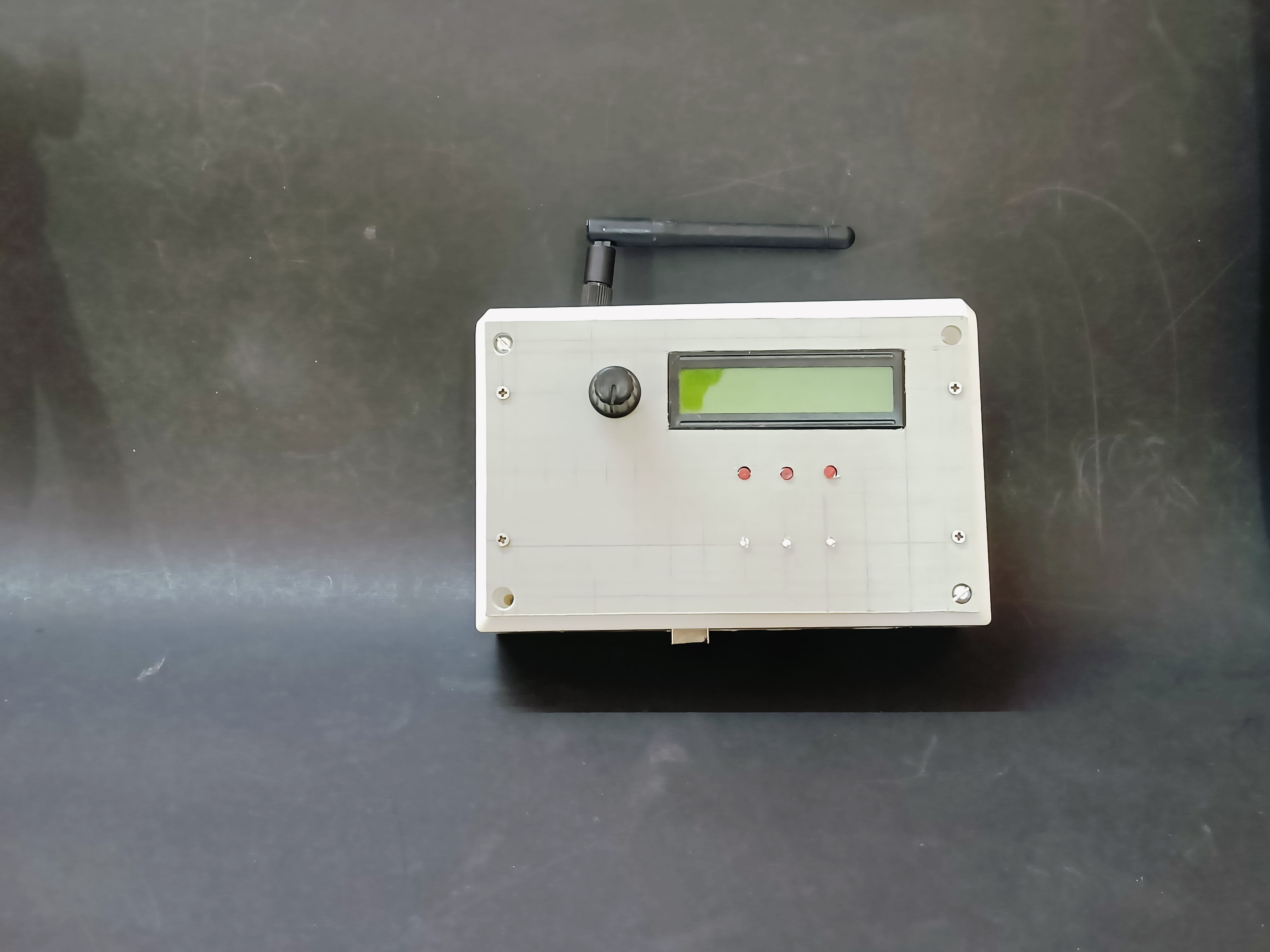
Soldering Station, Temperature Controlled
Multitool, Screwdriver
Drill / Driver, Cordless

Story

Read more

Custom parts and enclosures

Base Station

Schematics

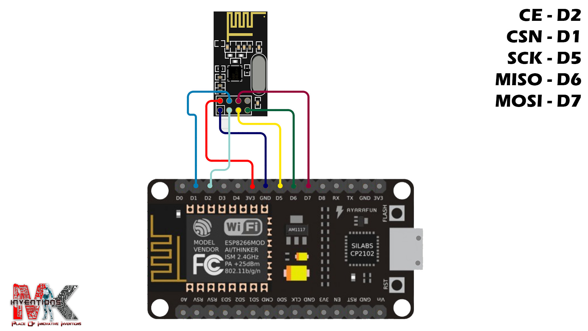
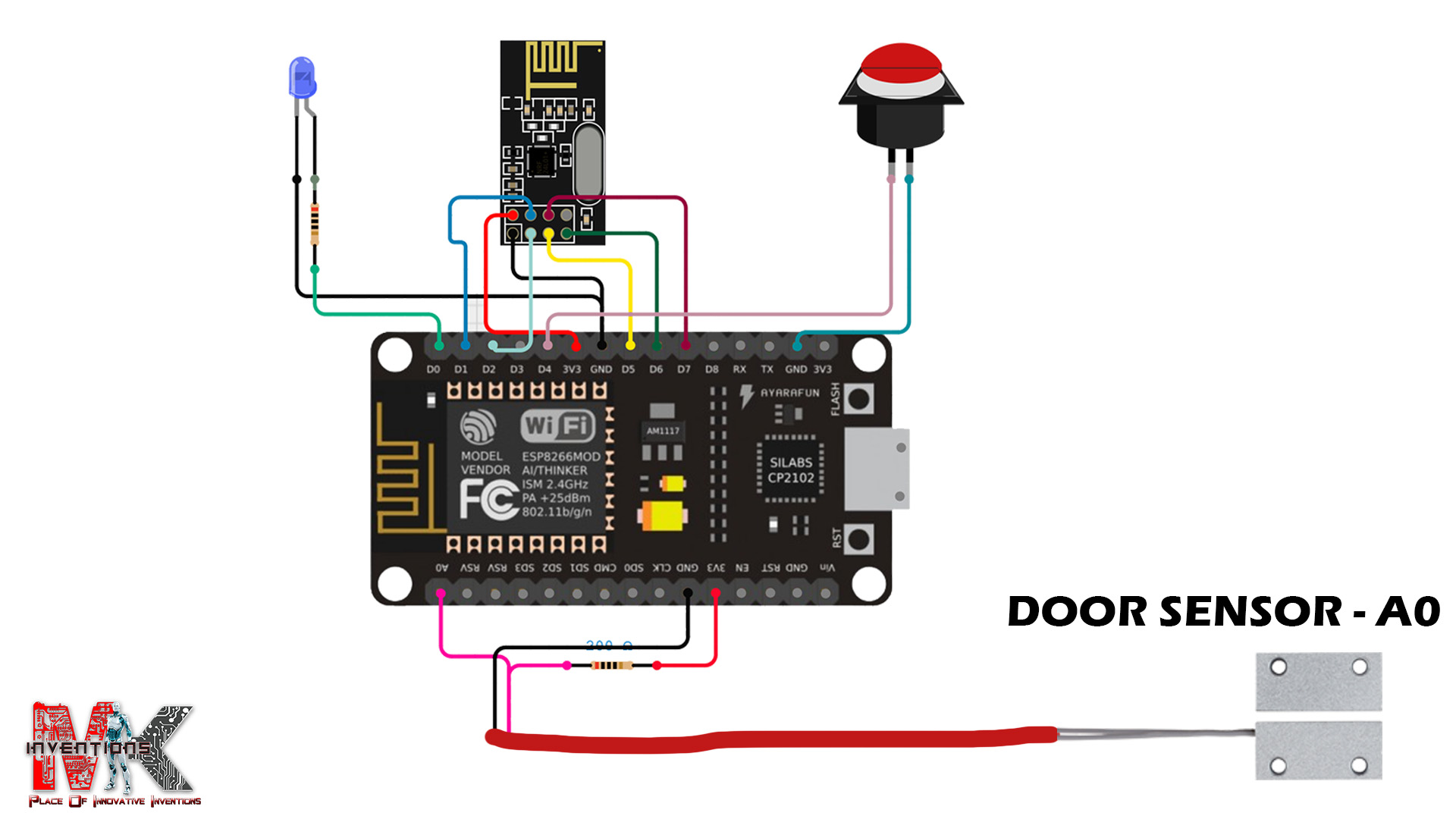
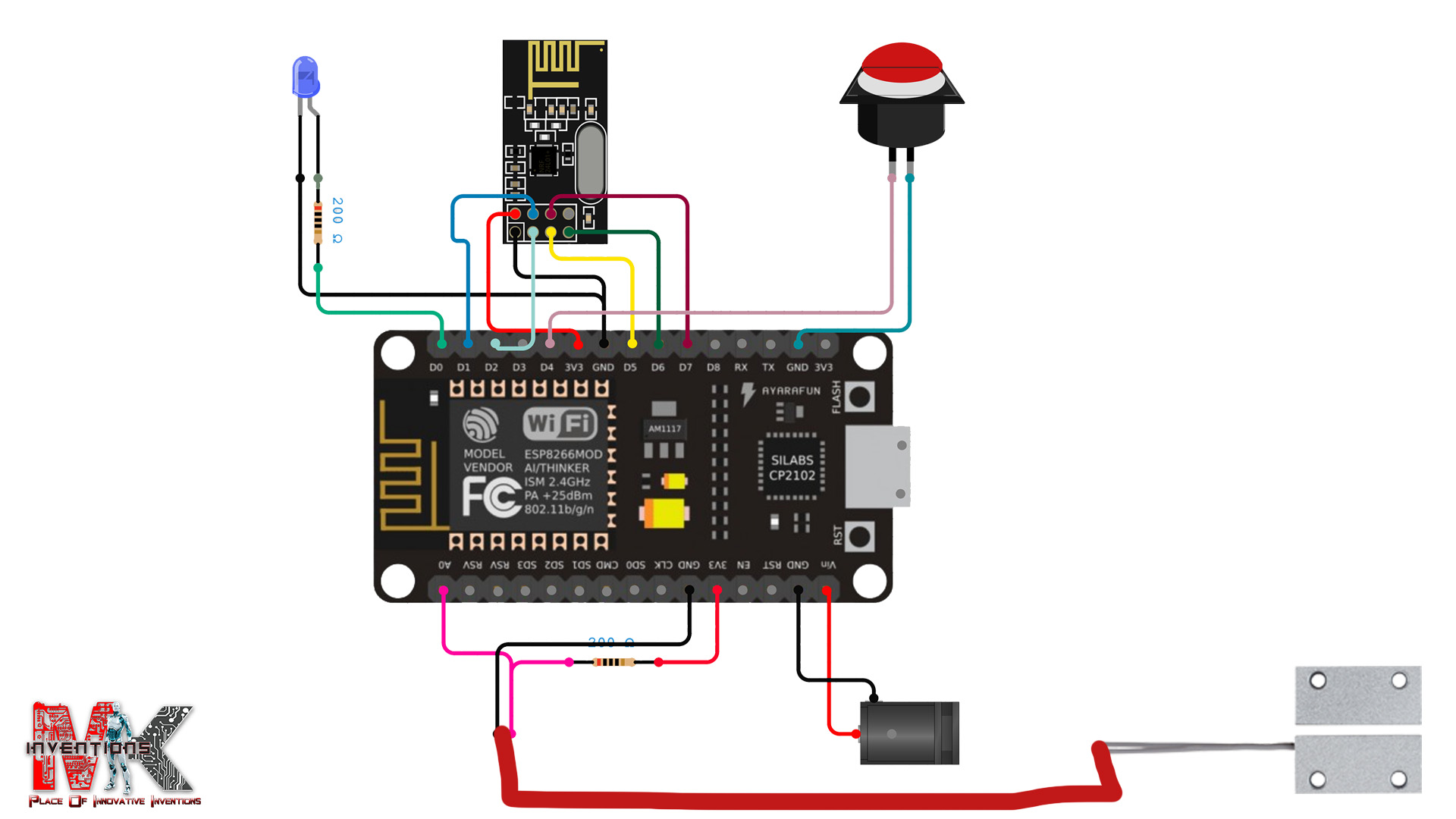
1️⃣ Interfacing NRF24L01 with ESP8266 (Door Sensor Unit)

The NRF24L01 is a wireless communication module used to transmit the door sensor data to Hub.

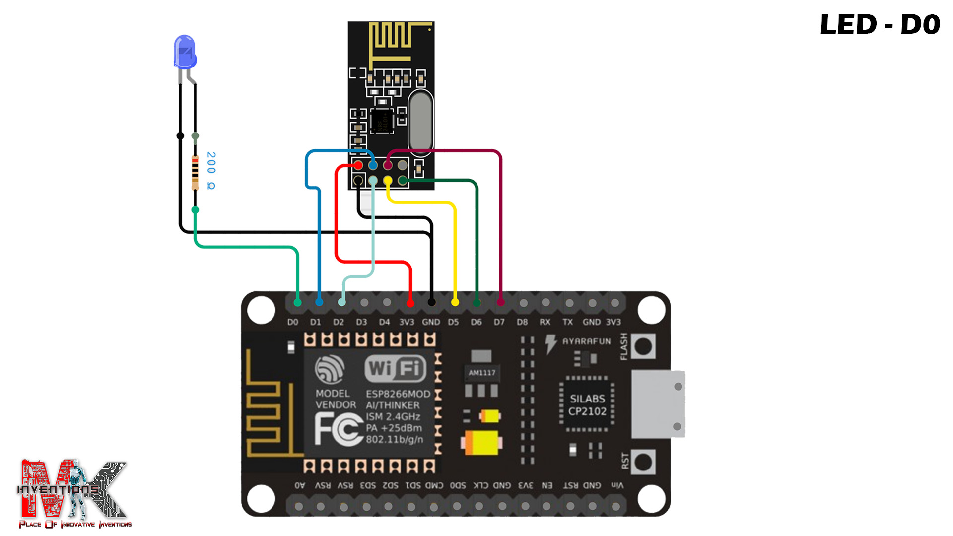
2️⃣ Interfacing LED with ESP8266

The LED is used as a status indicator for the door sensor when the door is open.

3️⃣ Interfacing Button with ESP8266

A push button is used to reset(boot) or restart the ESP8266. When pressed, it connects GPIO2 (D4) to GND, triggering a reset.

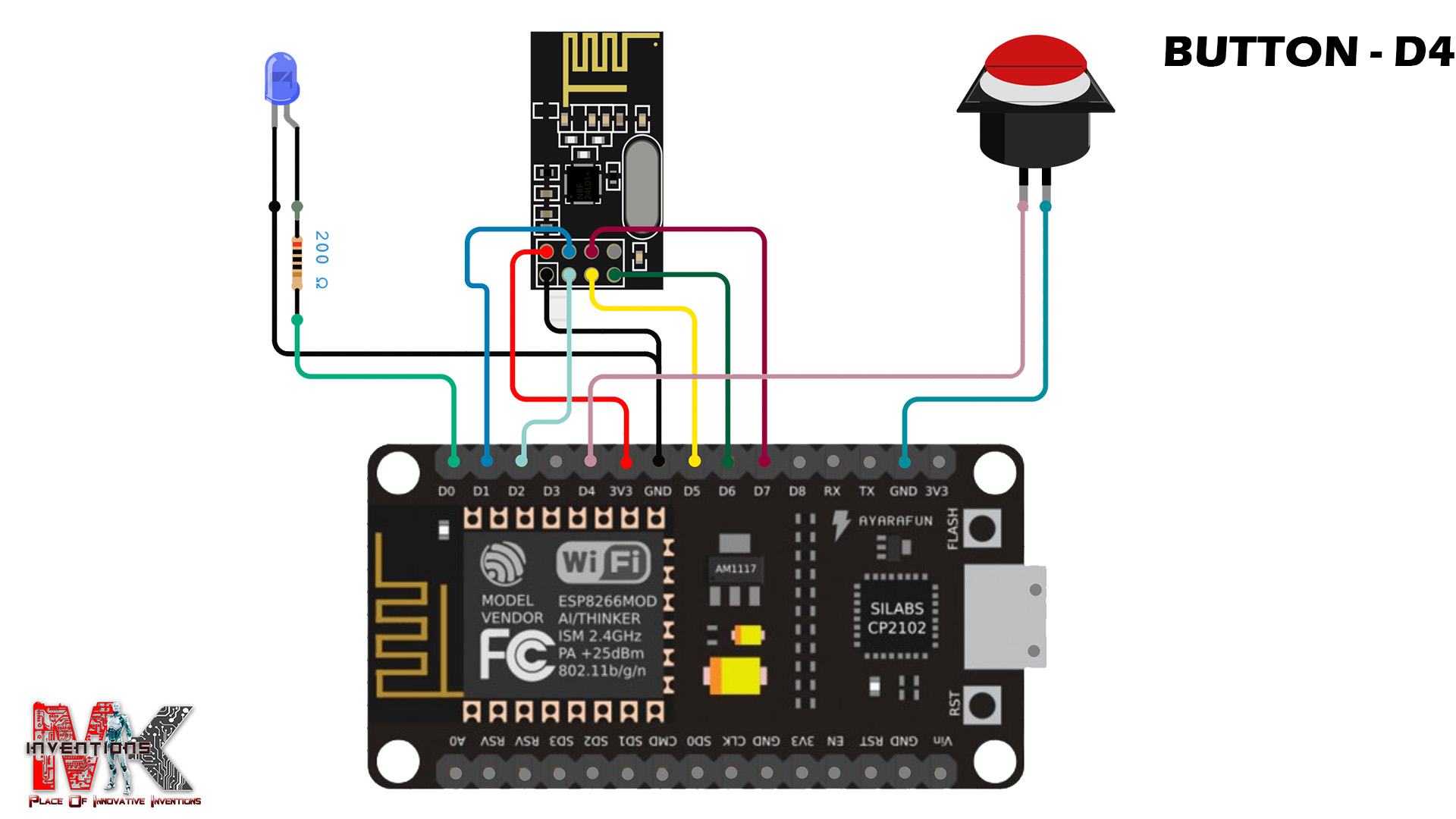
4️⃣ Interfacing Door Sensor with ESP8266 🚪🔍

The magnetic door sensor detects whether the door is open or closed by sending a signal to the ESP8266.

5️⃣ Interfacing DC Power Jack

For powering the ESP8266, a DC Jack (7v - 12V ) can be used with a Voltage Regulator.

Code

🔹 Code for Transmitter (ESP8266 - Door Sensor)

C/C++
/**
 * Project: ESP8266 Wireless Door Sensor using NRF24L01
 * Author: Madhan Chiruguri
 * Date: March 11, 2025
 * Description: This project uses an ESP8266 to monitor a door sensor and transmit the status
 * wirelessly using an NRF24L01 module. A button press triggers a software reset.
 */

#include <SPI.h>
#include <nRF24L01.h>
#include <RF24.h>

// Define RF24 radio module pins (CE, CSN) for ESP8266
RF24 radio(4, 5);
const byte address[6] = "10001";  // NRF24L01 communication address

// Define pin assignments
#define DOOR_SENSOR A0        // Analog input for the door sensor
#define DOOR_STATUS_LED 16     // LED to indicate door status
#define BUTTON 2               // Button input pin for triggering reset

// Structure to hold the data packet for transmission
struct data {
  uint8_t nodeId;      // Unique ID of the transmitting node
  uint8_t nodeState;   // Node status (1 = Active)
  uint8_t doorState;   // Door status (1 = Open, 0 = Closed)
};

void setup() {
  Serial.begin(9600);
  Serial.println("\nInitializing...");
  
  NRF24_Init();  // Initialize NRF24L01 module

  pinMode(DOOR_STATUS_LED, OUTPUT); // Set LED as output
  pinMode(BUTTON, INPUT_PULLUP);    // Use internal pull-up resistor for button
}

void loop() {
  int buttonValue = !digitalRead(BUTTON);  // Read button state (active low)
  int sensorValue = analogRead(DOOR_SENSOR);  // Read door sensor value

  // If button is pressed, perform a software reset
  if (buttonValue == 1) {
    Serial.println("Button Pressed! Restarting...");
    ESP.restart();  // Restart ESP8266
  }

  // Determine door state based on sensor value threshold
  int doorOpenState = (sensorValue > 700) ? 1 : 0;
  digitalWrite(DOOR_STATUS_LED, doorOpenState); // Update LED status

  // Prepare data packet
  struct data sendData = {1, 1, doorOpenState};

  // Send data with retry mechanism (max 3 attempts)
  for (int i = 0; i < 3; i++) {
    if (radio.write(&sendData, sizeof(sendData))) {
      Serial.print("Sent: ID:");
      Serial.print(sendData.nodeId);
      Serial.print(", State:");
      Serial.print(sendData.nodeState);
      Serial.print(", Door:");
      Serial.println(sendData.doorState);
      break;  // Transmission successful, exit loop
    } else {
      Serial.println("Transmission Failed! Retrying...");
      delay(500);  // Wait before retrying
    }
  }

  yield();  // Prevent watchdog reset by allowing background tasks
  delay(500);  // Delay to control loop execution speed
}

// Function to initialize the NRF24L01 module
void NRF24_Init() {
  if (!radio.begin()) {
    Serial.println("NRF24L01 Initialization Failed!");
    return;
  }
  radio.openWritingPipe(address);  // Set communication address
  radio.setPALevel(RF24_PA_LOW);   // Set power level for stability
  radio.setRetries(5, 15);         // Set retry attempts and delay
  // radio.setDataRate(RF24_250KBPS); // Uncomment to slow down SPI for stability
  radio.stopListening();           // Set as transmitter
  Serial.println("NRF24L01 Initialized Successfully!");
}

🔹 Code for Receiver (Arduino- Base Station)

C/C++
#include <SPI.h>
#include <nRF24L01.h>
#include <RF24.h>

RF24 radio(9, 10);  // CE, CSN
const byte address[6] = "10001";
 
#define BUZZER 7
#define DOOR_STATUS_LED A2
#define NODE_STATUS 

// Define data structure
struct data {
  uint8_t nodeId;
  uint8_t nodeState;
  uint8_t doorState;
};

unsigned long previousMillis = 0;
bool buzzerState = false;

// bool wasDisconnected = false; // Flag to track disconnection state

void setup() {
  Serial.begin(9600);
  Serial.println("\nInitializing...");

  pinMode(DOOR_STATUS_LED, OUTPUT);
  pinMode(BUZZER, OUTPUT);
  NRF24_Init();
}


void loop() {
  if (radio.available()) {
    struct data receiveData;
    radio.read(&receiveData, sizeof(receiveData));

    Serial.print("ID: ");
    Serial.print(receiveData.nodeId);
    Serial.print(", Status: ");
    Serial.print(receiveData.nodeState);
    Serial.print(", Door: ");
    Serial.println(receiveData.doorState);

    digitalWrite(DOOR_STATUS_LED, receiveData.doorState);
    // digitalWrite(BUZZER, receiveData.doorState == 1 ? HIGH : LOW);
    buzzer(receiveData.doorState, 100);
  }
}

void NRF24_Init() {
  if (!radio.begin()) {
    Serial.println("❌ NRF24L01 Initialization Failed!");
    return;
  }
  radio.openReadingPipe(1, address);
  radio.setPALevel(RF24_PA_MIN);
  radio.startListening();
  Serial.println("✅ NRF24L01 Initialized Successfully!");
}

void buzzer(int signal, int delayTime) {
  if (signal == 1) {
    if (millis() - previousMillis >= delayTime) {
      previousMillis = millis();
      buzzerState = !buzzerState;
      digitalWrite(BUZZER, buzzerState);
    }
  } else {
    digitalWrite(BUZZER, LOW);
  }
}

Credits

MKinventions Madhan Chiruguri
1 project • 2 followers
Contact

Comments

Please log in or sign up to comment.