Flip dot displays use a matrix of permanent electromagnets which flip a plastic disc. The advantages for commercial applications are that flip dots only require electricity when switching pixel positions. Once the pixels are set, no energy is required to keep them in their state, similar to an e-ink display. As the dots change state, they make noise, and rapidly flipping them can create a shaking animation. They are art as much as they are functional!
Alfa Zeta of Poland manufactures flip dot/disc displays in many configurations. Their XY5 display comes in 7x1, 7x7, 7x14, 7x28, and 14x28 and has a display driver already incorporated which uses the RS-485 interface and is powered by 24V DC. They come in either a 8.9mm disc or 13.5mm disc, the latter of which is shown here.
In this tutorial, an internet clock is made!
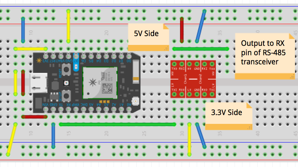
The photon is similar to the Arduino, however it operates at 3.3V rather than 5V. Many RS-485 transceivers use 5V logic, in which case a logic level converter is needed to translate 3.3V to 5V logic. The Sparkfun RS-485 transceiver breakout board uses a SP3485 IC rather than the MAX485 IC most commonly used. The SP3485 accepts 3.3V and 5V logic, so a logic level converter is not needed. The same result is achieved either way! Since we will only be transmitting to the display, only the TX pin will be used and not the RX pin on the photon.
The dip switches on the driver board allow for addressing and accessing test modes. The address used in this tutorial is 10000000 (only dip switch 1 is on) and dip switch #2 is 011 (1 off, 2 is on, and 3 is on).
To create fonts for the display, a binary byte is used. Lets take a look at an example.
A '1' represents a yellow dot, and a '0' represents a black dot. The display starts in the top right and moves leftward and down. A byte array is used to store the typeface. For example, number 3 is as follows...
byte numberThreeInBinary[] = {0b0111110, 0b0101010, 0b101010, 0b0100010};
In order, the bytes are 1, 2, 3, 4, which is right to left. An easy way to have a catalog of of numbers, is with a 2 dimensional array.
  byte numbersInBinary[][4]{
 {0b111110, 0b100010, 0b100010, 0b111110}, //zero
 {0b111110, 0b000000, 0b000000, 0b000000}, //one
 {0b111010, 0b101010, 0b101010, 0b101110}, //two
 {0b111110, 0b101010, 0b101010, 0b100010}, //three
 {0b001000, 0b111110, 0b001000, 0b111000}, //four
 {0b101110, 0b101010, 0b101010, 0b111010}, //five
 {0b001110, 0b001010, 0b001010, 0b111110}, //six
 {0b111110, 0b100000, 0b100000, 0b110000}, //seven
 {0b111110, 0b101010, 0b101010, 0b111110}, //eight
 {0b111110, 0b101000, 0b101000, 0b111000} //nine
};
Since an array starts at index 0 and increases, it's a convenient approach to accessing a number with a simple line of code such as this.
Serial1.write(numbersInBinary[num], 4);
As there are 28 columns on the display, in order to successfully transmit the time, all columns must be populated with a byte. Some extra characters can be useful such as a space which is an all black column, or a colon for separating the hours and minutes.
TransmittingTo tell the control board on the flip dots that a sequence of bytes will be sent by the photon, 3 bytes are sent out which initiate the transmission. Once all the remaining 28 bytes are sent out, a finalizing byte is communicated to end the process. The last of the 3 bytes is the address of the panel. These look like such:
byte startTransmission[] = {0x80, 0x83, 0b00000001};
//28 bytes of data e.g. Serial.write(numbersInBinary[3], 4);.....
byte endTransmission[] = {0x8F};
Serial1 on the Photon are the TX/RX pins while Serial is the usb port for debugging, which differs to the Arduino Uno where Serial is both the USB and pins. Here is an example transmission to make all the pixels white by passing an array of length 28 filled with 0's.
//Serial1.write(byteArray, length);
Serial1.write(startTransmission, 3);
Serial1.write(allWhite, 28);
Serial1.write(endTransmission, 1);
The flip dot display has a lot of potential when connected to the internet, and reading the time is just the start!
The code is commented which should help clarifying what each step is doing, but leave a comment if there is any confusion.


_3u05Tpwasz.png?auto=compress%2Cformat&w=40&h=40&fit=fillmax&bg=fff&dpr=2)
Comments
Please log in or sign up to comment.