


Hardware components | ||||||
_PnKPri8a6q.jpg?auto=compress%2Cformat&w=48&h=48&fit=fill&bg=ffffff) |
| × | 1 | |||
| × | 1 | ||||
| × | 1 | ||||
| × | 1 | ||||
 |
| × | 3 | |||
 |
| × | 3 | |||
In this post I am going to show how to use an Arduino board and BitVoicer Server to control a few LEDs with voice commands. I will be using the Arduino Micro in this post, but you can use any Arduino board you have at hand.
The following procedures will be executed to transform voice commands into LED activity:
- Audio waves will be captured and amplified by the Sparkfun Electret Breakout board;
- The amplified signal will be digitalized and buffered in the Arduino using its analog-to-digital converter (ADC);
- The audio samples will be streamed to BitVoicer Server using the Arduino serial port;
- BitVoicer Server will process the audio stream and recognize the speech it contains;
- The recognized speech will be mapped to predefined commands that will be sent back to the Arduino;
- The Arduino will identify the commands and perform the appropriate action.
The video above shows the final result of this post. Note in the video that BitVoicer Server also provides synthesized speech feedback. This speech feedback is defined in the server and reproduced by the server audio adapter, but the synthesized audio could also be sent to the Arduino and reproduced using a digital-to-analog converter (DAC). In my next post, I am going to show how to use the Arduino DUE, one amplified and one speaker to reproduce the synthesized speech using the Arduino itself.
List of Materials:
- Arduino Micro (or any other Arduino board): ~U$ 20.00
- Sparkfun Electret Microphone Breakout: U$ 7.95
- BitVoicer Server 1.0: U$ 9.90
- Breadboard: ~U$ 10.00
- 3 x LEDs: ~U$ 1.00
- 3 x 330 Ohms resistors: ~U$ 0.75
- Jumper wires: ~U$ 0.30
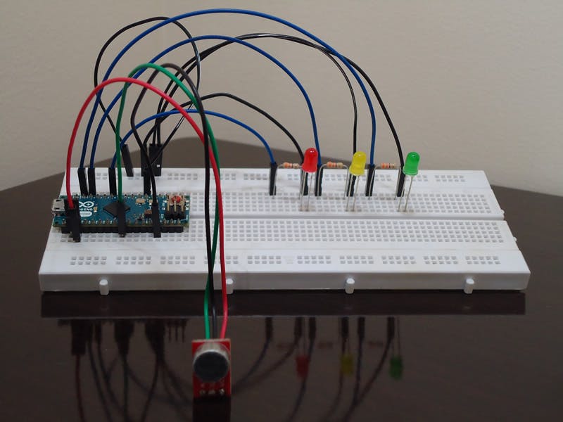
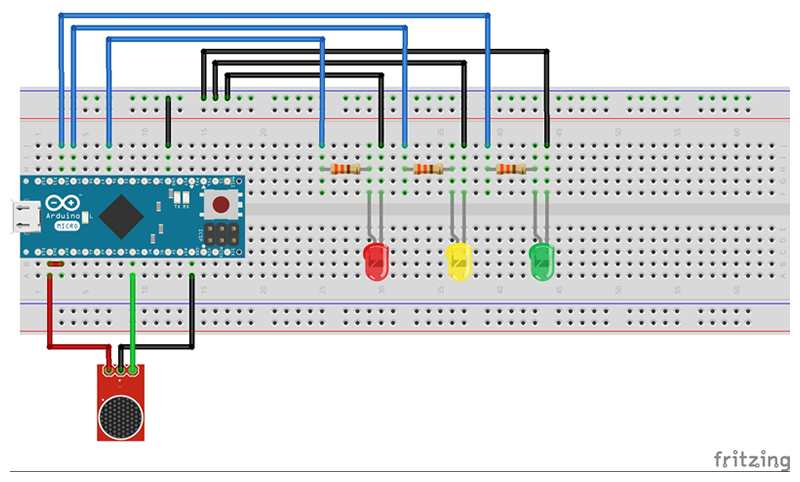
The first step is to wire the Arduino and the breadboard with the components as shown in the pictures below.
The most important detail here refers to the analog reference provided to the Arduino ADC. In my tests, I got better results using 3.3V with the Sparkfun Electret Breakout. That is why I added a jumper between the 3.3V pin and the AREF pin. If you decide to use the analogRead funcion (for any reason) while 3.3V is being applied to the AREF pin, you MUST call analogReference(EXTERNAL) before you use the analogRead function. Otherwise, you will short together the active reference voltage (internally generated) and the AREF pin, possibly damaging the microcontroller on your Arduino board.
Now you have to upload the code below to your Arduino. For convenience, the Arduino sketch is also available in the Attachments section at the bottom of this post. Before you upload the code, you must properly install the BitVoicer Server libraries into the Arduino IDE (Importing a .zip Library).
This sketch has four major parts:
- Library references and variable declaration: The first two lines include references to the BVSP and BVSMic libraries. These libraries are provided by BitSophia and can be found in the BitVoicer Server installation folder. The other lines declare constants and variables used throughout the sketch. The BVSP class is used to communicate with BitVoicer Server and the BVSMic class is used to capture and store audio samples.
- Setup function: This function initializes serial communication, the BVSP class, the BVSMic class and sets the “event handler” (it is actually a function pointer) for the frameReceived event.
- Loop function: This function performs three important actions: requests status info to the server (keepAlive() function), checks if the server has sent any data and processes the received data (receive() function), and controls the recording and sending of audio streams (isSREAvailable(), startRecording(), stopRecording() and sendStream() functions).
- BVSP_frameReceived function: This function is called every time the receive() function identifies that one complete frame has been received. Here I run the command sent from BitVoicer Server. The command contains 2 bytes. The first byte indicates the pin and the second byte indicates the pin value. I use the analogWrite() function to set the appropriate value to the pin.
Now you have to set up BitVoicer Server to work with the Arduino. BitVoicer Server has four major solution objects: Locations, Devices, BinaryData and Voice Schemas.
Locations represent the physical location where a device is installed. In my case, I created a location called Home.
Devices are the BitVoicer Server clients. I created a Mixed device, named it ArduinoMicro and entered the communication settings. NOTE ABOUT ARDUINO MICRO: it uses RTS and DTR so you have to enable these settings in the communication tab. I also created a SystemSpeaker device to synthesize speech using the server audio adapter.
BinaryData is a type of command BitVoicer Server can send to client devices. They are actually byte arrays you can link to commands. When BitVoicer Server recognizes speech related to that command, it sends the byte array to the target device. I created one BinaryData object to each pin value and named them ArduinoMicroGreenLedOn, ArduinoMicroGreenLedOff and so on. I ended up with 18 BinaryData objects in my solution, so I suggest you download and import the objects from the VoiceSchema.sof file below.
Voice Schemas are where everything comes together. They define what sentences should be recognized and what commands to run. For each sentence, you can define as many commands as you need and the order they will be executed. You can also define delays between commands. That is how I managed to perform the sequence of actions you see in the video.
You can import (Importing Solution Objects) all solution objects I used in this post from the files below. One contains the Devices and the other contains the Voice Schema and its Commands.
STEP 4: Conclusion
That is it! I hope you liked it.
You have everything you need to run the demo shown in the video. Note that in the video I started by enabling the ArduinoMicro device in the BitVoicer Server Manager. As soon as it gets enabled, the Arduino identifies an available Speech Recognition Engine and starts streaming audio to BitVoicer Server.
You can follow the recognition results in the Server Monitor tool available in the BitVoicer Server Manager.
In my next post I will show how you can reproduce synthesized speech using an Arduino DUE.


Comments
Please log in or sign up to comment.