Need something to tell you the temperature/humidity but also notify you when the temperature/humidity is not what you want it at? Then, build this device!
This device can accurately measure temperature and humidity and has customizable alarm thresholds. If the ambient temperature and humidity is not within the thresholds, then the device will light an LED and play an alert!
Functionality
https://drive.google.com/file/d/1fRtiY1ld17pjScPXQSuh3Vp7InmpA5Lm/view?usp=sharing -> Shows ambient humidity monitoring
https://drive.google.com/file/d/12sOJnK4gtz33RPCdyZiXo2B5kwppMRvE/view?usp=sharing -> Shows device beeping when the humidity is outside the designated threshold (30-58%) and the silence button
https://drive.google.com/file/d/12sOJnK4gtz33RPCdyZiXo2B5kwppMRvE/view?usp=sharing -> Shows adjustable thresholds. Press quickly to add one and hold to subtract one from the threshold value.
Build Instructions
Once your PocketBeagle is calibrated and soldered, begin to wire the device and download all corresponding code linked below. Also, be sure to download Python3.8. This website provides instructions on how to do so: https://linuxize.com/post/how-to-install-python-3-8-on-debian-10/. Then, run these download commands when your PocketBeagle is connected to Wi-Fi.
sudo python3.8 -m pip install upgrade setuptools
sudo python3.8 -m pip install Adafruit_BBIO
sudo python3.8 -m pip install adafruit-blinka
sudo python3.8 -m pip install adafruit-circuitpython-ahtx0
HT16K33 Displays
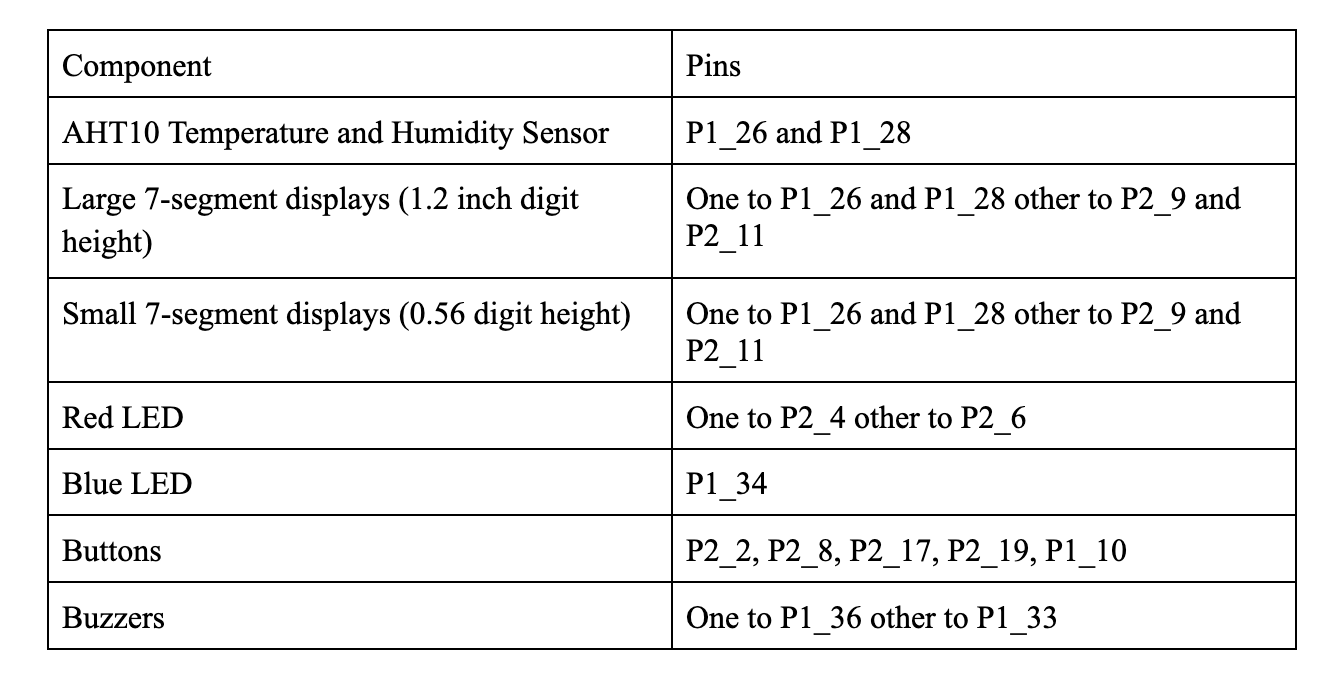
For the P1 Channel or I2C-2, the SDA pin is P1_26 and the SCL pin is P1_28. For the P2 Channel or I2C-1, the SDA pin is P2_11 and the SCL pin is P2_9. Both displays (large and small) need 3.3V and ground pins, and the large display needs an additional 3.3V.
Buttons
The buttons can be placed on any GPIO PocketBeagle pin. Feel free to adjust them as needed. On one metal leg of the button, a wire should connect it to the GPIO pin and a pull up resistor (1k-10k) should be connected to 3.3V. The other metal leg should be connected to ground.
LEDs
The long leg of the LED should be connected to its corresponding GPIO pin and its other leg should be connected to ground.
Buzzers
The red wire of the buzzer should be connected to its corresponding PWM pin and its other leg should be connected to ground.
Battery Power
If you want your device to run on boot, follow these commands run:
sudo crontab -e
Then, add this line:
@reboot sleep 30 && sh /var/lib/cloud9/ENGI301/project_01/code/run > /var/lib/cloud9/logs/cronlog 2>&1
Afterwards, test the DC-DC converter and make sure that it outputs 5V when inputted with voltages greater than 5V. You can use the 9V battery, alligator clips, a DMM, and a screwdriver to help verify this. Then, connect the battery power to the input of the DC-DC converter, connect its output to the Screw Terminal to Barrel Power Adapter, then plug that into the Barrel to MicroUSB converter. The MicroUSB will then go into the PocketBeagle!
You can use whatever housing you find most convenient to put all the electrical components in!


Comments
Please log in or sign up to comment.