The L298N module has a very famous L298 Motor driver IC which is the main part of this module. This module uses the PWM method to control the speed of DC motors.
Specifications of L298N Motor DriverThe module will allow you to control the speed and direction of two DC motors. It can control motors which operates between 5 to 35V and up to 2A. The module has an onboard regulator which helps in giving the output of 5V. The module can be powered from 5 to 35V from Arduino or external power supply. It is recommended to always use the external voltage supply. It can also control a stepper motor. It is inexpensive and perfect for robotic projects.
Pin out of L298N Motor DriverMotor A: This terminal block will give the output for the first motor.
12V Jumper: Keep this jumper in place if your supply voltage is less than 12V and the 5V power pin will give you the output of 5V. If the supply voltage is greater than 12V, then remove this jumper and give the 5V supply to the 5V power pin so that the L298 Dual H Bridge IC can work properly.
Power Pins: Give the supply voltage from 5 to 35V at the 12V pin and ground. If your supply voltage is greater than 12, then make sure to remove the 12V jumper. 5V pin will act as Output if the Vs will be less than 12V and 5V pin will act as Input if the Vs will be greater than 12V.
Enable Pins: Remove the jumpers on the Enable A and Enable B if you want to control the speed of DC motors and connect these to PWM pins of Arduino. If you want to control the stepper motor with L298N, then keep the jumper on Enable A and Enable B. Keeping the jumper on these pins means that the these pins will be High.
Logic Pins: Connect the Logic pins to any digital pins of Arduino. These will help in controlling the rotation and speed of DC motors.
Motor B: This terminal block will give the output for the second motor.
5V linear Regulator: This will step down the supply voltage to 5V and will give the output at the 5V pin.
The components required for this tutorial are as follows
- Arduino
- L298N Motor Driver Module
- 2 X DC Motors
- Joystick Module
- 12V Battery
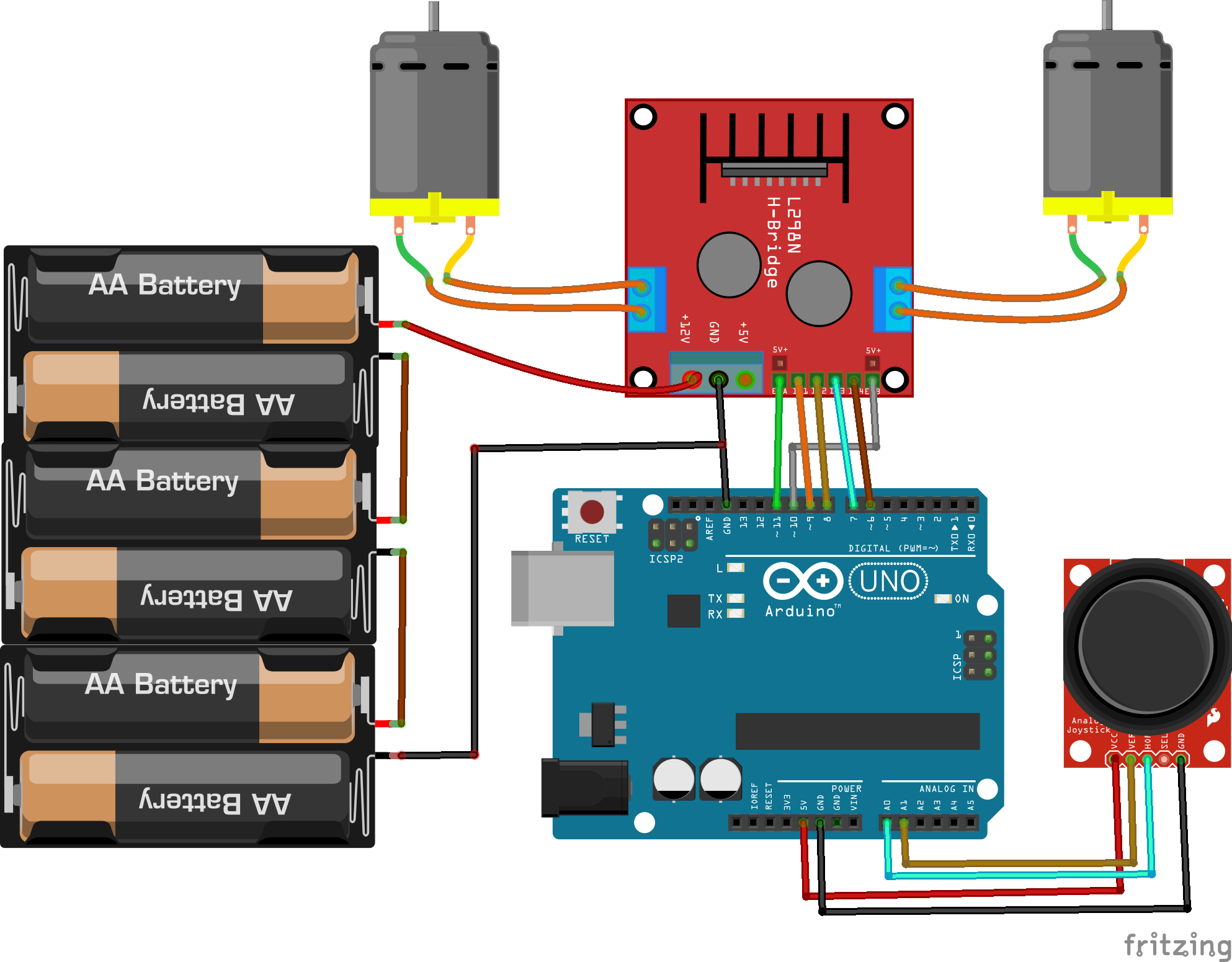
The circuit diagram for connecting the L298N motor driver module with the Arduino is shown below. Make the connections as follows
L298NArduino5 to 12V battery/Power SupplyENA Pin 11 IN1 Pin 9 IN2 Pin 8 IN3 Pin 7 IN4 Pin 6 ENB Pin 10 12V 5 to 12V power supply or battery GND GND Negative of power supply or battery In last, connect the two dc motors at the two sides of L298N
For powering the L298N, I have used the 2 rechargeable batteries of 3.7V.
Then connect the Joystick module with the Arduino as follows
Joystick ModuleArduinoVCC 5V VER A1 HOR A0 GND GND
//Joystick Pins
int x_key = A0;
int y_key = A1;
int x_pos;
int y_pos;
//Motor Pins
int EN_A = 11;      //Enable pin for first motor
int IN1 = 9;       //control pin for first motor
int IN2 = 8;       //control pin for first motor
int IN3 = 7;        //control pin for second motor
int IN4 = 6;        //control pin for second motor
int EN_B = 10;      //Enable pin for second motor
//Initializing variables to store data
int motor_speed;
int motor_speed1;
void setup ( ) {
Serial.begin (9600); //Starting the serial communication at 9600 baud rate
//Initializing the motor pins as output
pinMode(EN_A, OUTPUT);
pinMode(IN1, OUTPUT);
pinMode(IN2, OUTPUT);
pinMode(IN3, OUTPUT);
pinMode(IN4, OUTPUT);
pinMode(EN_B, OUTPUT);
//Initializng the joystick pins as input
pinMode (x_key, INPUT) ;
pinMode (y_key, INPUT) ;
}
void loop () {
x_pos = analogRead (x_key) ;  //Reading the horizontal movement value
y_pos = analogRead (y_key) ;  //Reading the vertical movement value

if (x_pos < 400){     //Rotating the left motor in clockwise direction
motor_speed = map(x_pos, 400, 0, 0, 255);   //Mapping the values to 0-255 to move the motor
digitalWrite(IN1, LOW);
digitalWrite(IN2, HIGH);
analogWrite(EN_A, motor_speed);
}
else if (x_pos>400 && x_pos <600){  //Motors will not move when the joystick will be at center
digitalWrite(IN1, LOW);
digitalWrite(IN2, LOW);
}

else if (x_pos > 600){    //Rotating the left motor in anticlockwise direction
motor_speed = map(x_pos, 600, 1023, 0, 255);
digitalWrite(IN1, HIGH);
digitalWrite(IN2, LOW);
analogWrite(EN_A, motor_speed);
}

if (y_pos < 400){         //Rotating the right motor in clockwise direction
motor_speed1 = map(y_pos, 400, 0, 0, 255);
digitalWrite(IN3, LOW);
digitalWrite(IN4, HIGH);
analogWrite(EN_B, motor_speed1);
}
else if (y_pos>400 && y_pos <600){
digitalWrite(IN3, LOW);
digitalWrite(IN4, LOW);
}

else if (y_pos > 600){        //Rotating the right motor in anticlockwise direction
motor_speed1 = map(y_pos, 600, 1023, 0, 255);
digitalWrite(IN3, HIGH);
digitalWrite(IN4, LOW);
analogWrite(EN_B, motor_speed1);
}
}After making sure everything works fine on the breadboard, I have designed the PCB on KiCad.
Following is a link to the project folder of this project.
After designing the PCB’s, I generated the Gerber file needed for the manufacturing of PCB.
You can download the Gerber file through the following link
10 – Arduino L298N gerberDownload
Ordering the PCBsNow we have got the PCB design and it’s time to order the PCB’s. For that, you just have to go to JLCPCB.com, and click on “QUOTE NOW” button.
JLCPCB are also sponsor of this project. JLCPCB (Shenzhen JLC Electronics Co., Ltd.), is the largest PCB prototype enterprise in China and a high-tech manufacturer specializing in quick PCB prototype and small-batch PCB production. You can order a minimum of 5 PCBs for just $2.
To get the PCB manufactured, upload the gerber file you downloaded in the last step. Upload the.zip file or you can also drag and drop the gerber files.
After uploading the zip file, you’ll see a success message at the bottom if the file is successfully uploaded.
You can review the PCB in the Gerber viewer to make sure everything is good. You can view both top and bottom of the PCB.
After making sure our PCB looks good, we can now place the order at a reasonable price. You can order 5 PCBs for just $2 but if it’s your first order then you can get 10 PCBs for $2.
To place the order, click on “SAVE TO CART” button.
My PCBs took 2 days to get manufactured and arrived within a week using DHL delivery option. PCBs were well packed and the quality was really good.
After assembling everything here is how it looks like.
//Motor Pins
int EN_A = 6;      //Enable pin for first motor
int IN1 = 10;       //control pin for first motor
int IN2 = 9;       //control pin for first motor
int IN3 = 8;        //control pin for second motor
int IN4 = 7;        //control pin for second motor
int EN_B = 5;      //Enable pin for second motor
int motor_speed;
int motor_speed1;
void setup ( ) {
//Initializing the motor pins as output
pinMode(EN_A, OUTPUT);
pinMode(IN1, OUTPUT);
pinMode(IN2, OUTPUT);
pinMode(IN3, OUTPUT);
pinMode(IN4, OUTPUT);
pinMode(EN_B, OUTPUT);
analogWrite(EN_A, 255);
analogWrite(EN_B, 255);
}
void loop () {
digitalWrite(IN1, LOW);
digitalWrite(IN2, HIGH);
digitalWrite(IN3, LOW);
digitalWrite(IN4, HIGH);
delay(3000);
digitalWrite(IN1, LOW);
digitalWrite(IN2, LOW);
digitalWrite(IN3, LOW);
digitalWrite(IN4, LOW);
delay(1000);
digitalWrite(IN1, HIGH);
digitalWrite(IN2, LOW);
digitalWrite(IN3, HIGH);
digitalWrite(IN4, LOW);
delay(3000);
digitalWrite(IN1, LOW);
digitalWrite(IN2, LOW);
digitalWrite(IN3, LOW);
digitalWrite(IN4, LOW);
delay(1000);
}If you have any questions, feel free to ask us in the comment section.


Comments
Please log in or sign up to comment.