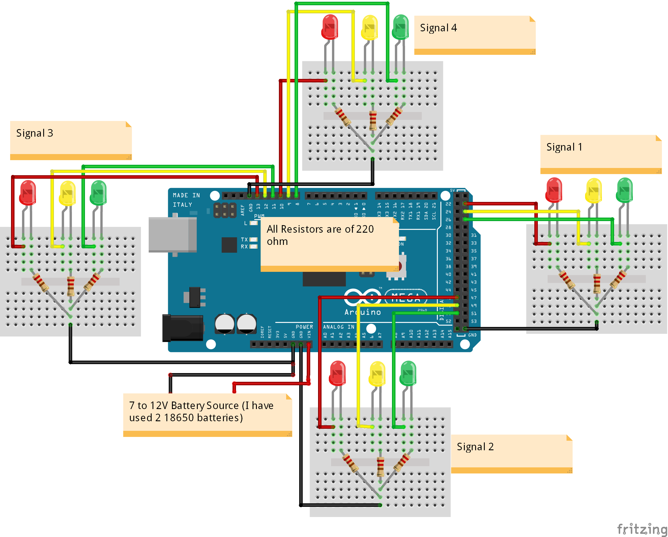
In this post, you are going to learn about how to make an Arduino traffic light controller. This traffic light controller will be used to control the flow of traffic. These can be applied at high traffic areas to avoid traffic blocks or accidents.
The main part of this project is the Arduino which will control the LEDs and their timings to guide the vehicles.
I also made an Density based traffic light controller using Arduino. Don’t forget to take a look at that.
For Custom Projects, hire me at https://www.freelancer.com/u/Muhammadaqibdutt
Working of Arduino Traffic Light ControllerThis project is done to give you an idea of how the traffic light controller works. This is not the real time traffic light controller.
So at start, green light of signal 1 and red lights at other signals will light up to give time to the vehicles at signal 1 to pass.
After 5 seconds, the yellow light at signal 1 will light up to give an indication that the red light at signal 1 is about to come up and also to give an indication to the vehicles at signal 2 that the green light is about to light up.
So after 2 seconds, red light at signal 1 will come up and green light at signal will come up meaning vehicles at signal 1 must stop and vehicles at signal 2 can move.
Similarly the traffic light controller will work for the signal 3, signal 4 and the system will keep looping.
Components Required for Arduino Traffic Light ControllerThe components you will be required for Arduino traffic light controller are as follows
- Arduino Mega 2560
- Red LEDs (4 pieces)
- Yellow LEDs (4 pieces)
- Green LEDs (4 pieces)
- 220 ohm resistors (12 pieces)
- Jumper cables
- Breadboards
There are total of 12 LEDs used in this project. Each signal has 3 LEDs (Red, Yellow and Green) connected to it through the 220 ohm resistors.
The resistors are used to limit the current that is going to pass through the LEDs. If you won’t use the resistors then the LEDs may burn due to excessive current.
Read More:
First of all, we initialized four arrays for the signal pins and defined the pins where we have connected the LEDs.
int signal1[] = {23, 25, 27};
int signal2[] = {46, 48, 50};
int signal3[] = {13, 12, 11};
int signal4[] = {10, 9, 8};
Then in the setup function, we declared all the pins as output so that we can control these with the Arduino.
for (int i = 0; i < 3; i++) {
    pinMode(signal1[i], OUTPUT);
    pinMode(signal2[i], OUTPUT);
    pinMode(signal3[i], OUTPUT);
    pinMode(signal4[i], OUTPUT);
  }
In the loop function, we controlled the signal one by one to control the flow of traffic.
digitalWrite(signal1[2], HIGH);
  digitalWrite(signal1[0], LOW);
  digitalWrite(signal2[0], HIGH);
  digitalWrite(signal3[0], HIGH);
  digitalWrite(signal4[0], HIGH);
  delay(redDelay);
  digitalWrite(signal1[1], HIGH);
  digitalWrite(signal1[2], LOW);
  delay(yellowDelay);
  digitalWrite(signal1[1], LOW);
  digitalWrite(signal1[0], HIGH);
  digitalWrite(signal2[2], HIGH);
  .
  .
.int signal1[] = {23, 25, 27};
int signal2[] = {46, 48, 50};
int signal3[] = {13, 12, 11};
int signal4[] = {10, 9, 8};
int redDelay = 5000;
int yellowDelay = 2000;
void setup() {
// Declaring all the LED's as output
for (int i = 0; i < 3; i++) {
pinMode(signal1[i], OUTPUT);
pinMode(signal2[i], OUTPUT);
pinMode(signal3[i], OUTPUT);
pinMode(signal4[i], OUTPUT);
}
}
void loop() {
// Making Green LED at signal 1 and red LED's at other signal HIGH
digitalWrite(signal1[2], HIGH);
digitalWrite(signal1[0], LOW);
digitalWrite(signal2[0], HIGH);
digitalWrite(signal3[0], HIGH);
digitalWrite(signal4[0], HIGH);
delay(redDelay);
// Making Green LED at signal 1 LOW and making yellow LED at signal 1 HIGH for 2 seconds
digitalWrite(signal1[1], HIGH);
digitalWrite(signal1[2], LOW);
delay(yellowDelay);
digitalWrite(signal1[1], LOW);
// Making Green LED at signal 2 and red LED's at other signal HIGH
digitalWrite(signal1[0], HIGH);
digitalWrite(signal2[2], HIGH);
digitalWrite(signal2[0], LOW);
digitalWrite(signal3[0], HIGH);
digitalWrite(signal4[0], HIGH);
delay(redDelay);
// Making Green LED at signal 2 LOW and making yellow LED at signal 2 HIGH for 2 seconds
digitalWrite(signal2[1], HIGH);
digitalWrite(signal2[2], LOW);
delay(yellowDelay);
digitalWrite(signal2[1], LOW);
// Making Green LED at signal 3 and red LED's at other signal HIGH
digitalWrite(signal1[0], HIGH);
digitalWrite(signal2[0], HIGH);
digitalWrite(signal3[2], HIGH);
digitalWrite(signal3[0], LOW);
digitalWrite(signal4[0], HIGH);
delay(redDelay);
// Making Green LED at signal 3 LOW and making yellow LED at signal 3 HIGH for 2 seconds
digitalWrite(signal3[1], HIGH);
digitalWrite(signal3[2], LOW);
delay(yellowDelay);
digitalWrite(signal3[1], LOW);
// Making Green LED at signal 4 and red LED's at other signal HIGH
digitalWrite(signal1[0], HIGH);
digitalWrite(signal2[0], HIGH);
digitalWrite(signal3[0], HIGH);
digitalWrite(signal4[2], HIGH);
digitalWrite(signal4[0], LOW);
delay(redDelay);
// Making Green LED at signal 4 LOW and making yellow LED at signal 4 HIGH for 2 seconds
digitalWrite(signal4[1], HIGH);
digitalWrite(signal4[2], LOW);
delay(yellowDelay);
digitalWrite(signal4[1], LOW);
}If you have any questions, feel free to ask us in the comment section.


_wzec989qrF.jpg?auto=compress%2Cformat&w=48&h=48&fit=fill&bg=ffffff)


Comments
Please log in or sign up to comment.