


Hardware components | ||||||
| × | 1 | ||||
| × | 1 | ||||
| × | 1 | ||||
 |
| × | 1 | |||
 |
| × | 1 | |||
 |
| × | 1 | |||
| × | 1 | ||||
| × | 1 | ||||
Software apps and online services | ||||||
 |
| |||||
| ||||||
Hand tools and fabrication machines | ||||||
 |
| |||||
 |
| |||||
| ||||||
| ||||||
| ||||||
| ||||||
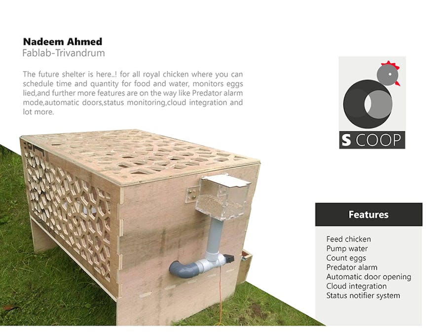
I'm thinking of switching to a chicken coop with some embedded features such as:
- Automatic feeder system.
- Automatic water dispenser.
- Egg collector and Notification system.
- Predator alarm.
The coop will be made with plywood (shopbot) and mesh. It will use custom designed boards as controllers, and I will develop a mobile phone application in which user can check the coop status. First I thought of a GSM module as transmission medium then switched to Bluetooth. I will use a 3D printer and laser cutter for the feeder system designs. The feeder system will use an auger and a servo. An IR sensor will be used to sense the eggs and send a notification through the GSM module each time an egg is laid. I am planning on using a slanted mesh base on some comfortable angle for the chickens, so you can collect the eggs in the egg tray.
What will the controller do?- control and feed timing and quantity.
- control water flow.
- sense eggs and send notifications.
- sense predators.
This is the first rough sketch for the base skeleton I made in my mobile application. I have made considerable changes since I started. First I decided to use mesh. Then I designed the plywood pattern using a so called voronoi structure, which looks like asymmetric honey comb mesh.
I planned to tack mesh to the frame to provide sunlight and airflow, but I planned to design asymmetric honey comb mesh so called voronoi.
The main visible part of my project is the wooden structure, which I designed in Rhino with the help of grasshopper. The basic design parameters I followed are:
- Material extrusion: 12 mm
- Pressfit tolerance: 5 mm
Here I used tolerance as 5 mm so as to make press-fit joints tight. Also my plywood was warped so I had to to change the design according to my material quality and consistency.
To be frank it was a mess when I did it for the first time and I felt a bit slow mapping the functions to their respective curves or surfaces in grasshopper. Grasshopper design files. That's how I made my 2 piece of wood into voronoi, the upper part and front part.
Shopbot: WoodworkingAll design set to mill, using Vcarve. I have arranged the work on the plywood in such a way that it fits exactly. I used an entire 8 ft x 4 ft sheet and an additional piece of 80 cm x 80 cm for a single coop. I have generated vcarve files by keeping in mind the common facts given below:
- Bit using
- Diameter of the bit that can fit in so as to make edges.
I used the below setting for milling my design. Here the Spindle speed is 12000 RPM and plunge rate is 25, feed rate is 45 and pass depth 3.2 also I am using 1/4" upcut and 1/4" ballnose upcut for engrave and pocket.
Loaded the material on shopbot and ready to go! With help from my mates, I have managed to assemble it. We used a dremel tool and file to smooth the exposed edges and tab remains etc.
Video showing the cutting of voronoi structure.
Almost done with the coop structure, now I have to design a hay-box (egg collector box). I used Rhino for this as well. I milled the design with the shopbot. The image shows the hay-box assembly.
I set the cut depth as 12.5 mm even though the material thickness is 12 mm. Due to the uneven surface of my plywood, I did't get a good cut so I needed a lot of effort on filing, I became a filing expert though. I used a dremel tool and file to fix the same.
Mission accomplished!
Acrylic PartsThe acrylic parts use a simple press fit design. The purpose is to make containers for food and water. I used a 6 mm clear acrylic so that we can see the quantity in it. I am using craft-wood as the top since we have 3 mm craft-wood in-order to smooth the opening and closing. In my Rhino design I left some extra material to lap over the sides of the box. I mounted it with screws. I measured my screw diameter with vernier caliper so I can cut holes that will line up.
Before getting it right, I did a test runs with my dimensions to see what fits best. This helped me a lot to get the press fit exactly how I wanted.
Auger Design and 3D-printI'm using an auger to move feed from storage to the feeder box. Here I need an auger shape where its base is connected to servo motor. I started designing in Rhino.
Making the Servo ContinuousI took the normal servo and removed all screws then de-soldered its connections so that I could see what was inside. Then I pulled out entire components inside it.
Then on the other side where rotor spindle is I found another set of screws. I opened the gear case. Using my dremel tool I sliced it off. After that, I checked the rotation, even now its only 180 degree max. I found that inside the small metal case there was a feedback potentiometer which prevented the rotation.
Hurray! It's rotating 360 degrees, I have done all the mechanical part of it. I didn't know any electronic or software limitations, so I connected my servo board that I made in output week and tested it to find out if it was all fine.
Then I attached the auger I made to the servo and tested it. The below video shows the working of servo with auger attached.
Controller boardFor controlling and coordinating all of the functions in the chicken coop, which in the first stage includes servo control, water pump control and IR module. Later on I want to add camera and thermal scanner, etc.
So first I decided to make my own controller using the Attiny 45. I started designing in Eagle.
Application Interfacing Using BluetoothThis part will make the smart coop a bit smarter, since I am enabling the user to access the coop remotely. I will make use of only 4 pins which are VCC, GND, RX, and TX.
Here I am using MIT app inventor to create my application used for the interfacing of the device with the mobile application, which follows scratch based developing platform managed to drag the blocks as shown in the image for my functionalities.
Once authenticated go to:
Projects -> Start new project
And its done, ready to go! It's very easy to use, just drag an drop the functions we need in a graphical environment. Since I did the same in my interfacing week it's was easy, and I didn't have to invest much time on it since all worked fine.
Water dispenserWhat I wanted is to connect a water dispenser to my chicken coop so as to control it from a mobile app. I used a 12V DC pump which is attached to the water container. My plan is to connect this pump to a motor driver and use MIT app inventor application to drive it.
I used the L293D motor driver IC module which is typically used to drive motors in both the directions since I have the same functionality I will be using the 16-pin board to drive my 12V DC pump here. So in the code I just have to enable the pin high when invoked.
Here goes the pump attached to the coop where one end is left inside the coop for replenishing the water bowl inside and the other is connected to water container.
Egg counterI wanted to attach a small Egg counter module so as to count the same and display it on my mobile phone, I used the below logic for designing the IR circuit.
Designed in Eagle with modification and adding the ISP and pin headers to the circuit.
Sadly this board is "NOT" working as I expected it to be. I have put some time on the board but I was not able to do it, the deadline for presentation is approaching so I switched to use a IR module so as to connect it to my controller board. The module is working fine for my counting functionality.
This stitched images represents UI of all 3 functionalities, that is servo, egg counter and water pump respectively.
You can download my design files here:


_3u05Tpwasz.png?auto=compress%2Cformat&w=40&h=40&fit=fillmax&bg=fff&dpr=2)
Comments
Please log in or sign up to comment.