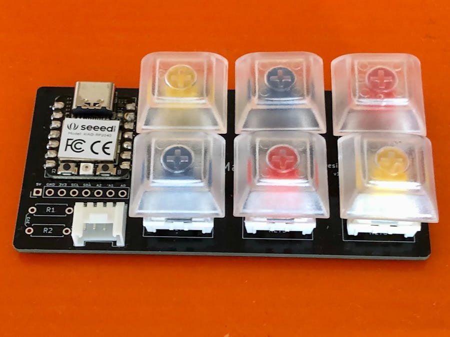
I always wanted to make a DIY Macropad myself. In this project, we will go through the process of making a 6-keys Macropad using a Seeed Studio XIAO RP2040 which is a tiny development board. This is my first PCB design project using KiCad EDA.
Hardware componentsFirst, we have to decide about what are we going to use in this project. In my case, I am going to use the following components.
XIAO RP2040
It will be used as an interface between keys GPIOs and the computer over a serial connection.
Mechanical Keys
Keycaps
We do not want to use the keys without a cap!
Hot-swap Sockets
They are used to mount the keys without soldering the keys to the PCB. We will be soldering the sockets on the back of the PCB and we can hot-swap compatible mechanical keys whenever we like to do so.
Grove Female Header
We can connect them to XIAO RP2040 I2C pins to use Grove compatible sensors, just for future-proof!
I will be using MacOS for development purposes. Please install KiCad EDA (version 6.0.x) from here and follow installation instructions for your operating system. To create a new project, click on File > New Project and give it a name. We can see the start screen as shown below.
Currently, there is no symbol and footprint library for KiCad available for XIAO RP2040. But the Seeduino XIAO's footprint is the same as that of XIAO RP2040 so we will be repurposing them for this project. Please follow the instructions here to import libraries into KiCad. We also need to import Seeed Fusion PCBA Open Parts Library if we want to use the Grove connector symbol and footprint. To use the Kailh mechanical keys with hot-swap socket footprint, we would need to import Switch_Keyboard_Hotswap_Kailh from the Keyswitch Kicad Library. Once we are done with all imports we can proceed to create schematics.
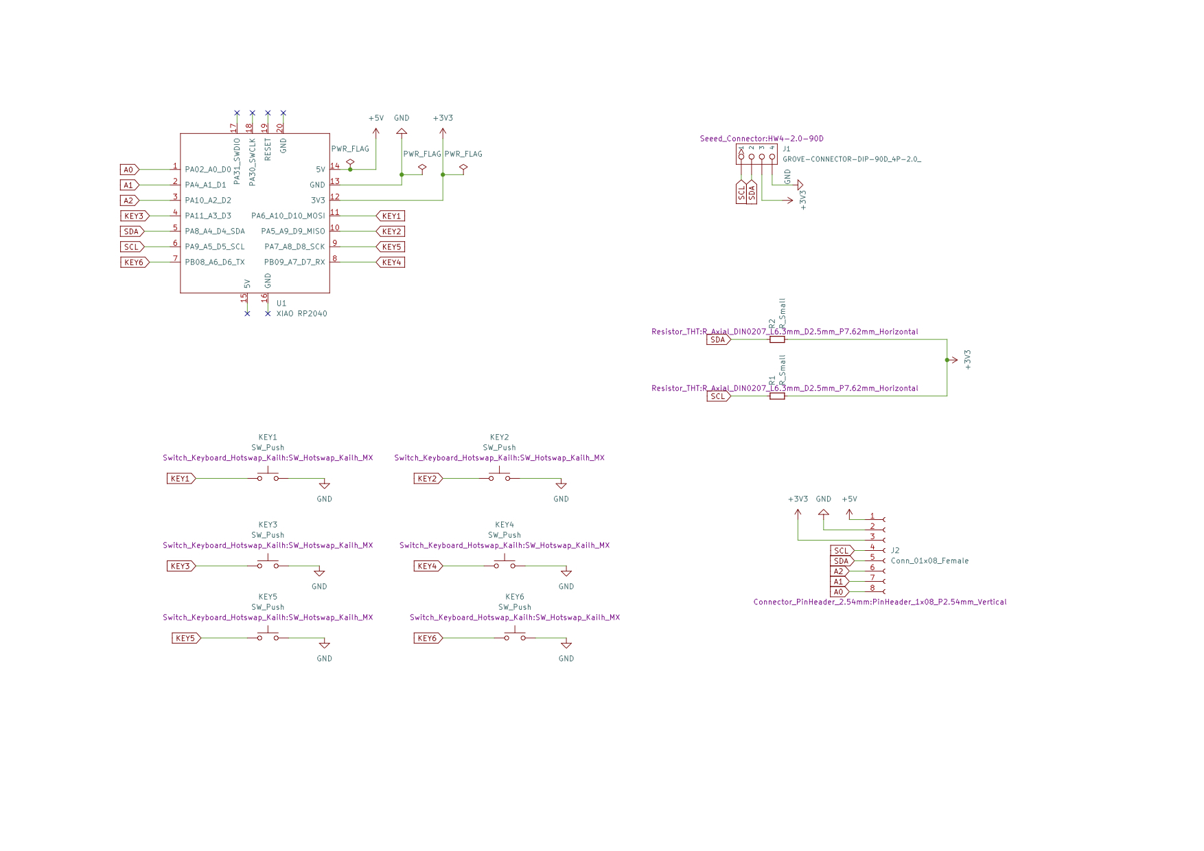
SchematicsOpen the Schematics editor, choose Place > Add Symbol from the top menu and search for Seeed_XIAO and select SeeeduinoXIAO as shown below.
After adding the symbol, double click on the symbol which would open the Symbol Properties window where we can add a footprint. Also, we can rename it to XIAO RP2040 as shown below.
Now we can add labels and connections to the symbols as shown below.
Likewise, we can add 6 symbols and footprints for Kailh switches. The symbols are generic switch symbols from the KiCad library and the footprint is chosen from the imported Switch_Keyboard_Hotswap_Kailh library.
Similarly, we can add Grove connector and other pin headers symbols.
We should check using the Inspect > Electrical Rules Checker menu to make sure everything is OK, otherwise go and fix the issues by reading the messages one by one. Once we are done with adding/fixing the symbols we can open the PCB Editor.
PCB DesignWe should choose Tools > Update PCB from Schematics... to update the PCB view to the latest changes. We can arrange the footprints and route the tracks here. it is an iterative process and we have to go back and forth between Symbol Editor and PCB Editor to make corrections and changes. We should avoid routing the track initially, once we are done with the placement and alignment of most of the footprints we can route tracks. We should always check using the Inspect > Design Rules Checker menu to make sure everything is OK, otherwise go and fix the issues by reading the messages one by one. We can insert any text or logo on the silkscreen. Below is the final version of the design.
We can see the 3D view of the PCB by choosing View > 3D Viewer.
When we are confident that the design is good enough and error-free we can go ahead with PCB manufacturing. Every PCB manufacturer has its specific requirement for submitting the Gerber and drill files. Please check with them beforehand. I used the Seeed Studio Fusion service for this project. Please follow the instructions here to generate Gerber and drill files. After creating the required files we can submit them to the Fusion service.
After receiving the fabricated PCBs we should do a continuity check using a multimeter to make sure there are no shorts, just in case. Below are the fabricated PCB images.
Front
Back
We need to do soldering the XIAO RP2040, Grove connector, and the hot-swap sockets. The XIAO RP2040 is used as a module on the PCB and soldered directly on the SMD pads.
Front
Back
After mounting switches and keycaps it looks like as below.
Now it's time to test if it would work as expected. Below is the basic demo code to test the Macropad functionalities. It simply turns on/off the onboard Red, Blue, and Green LEDs on each key press.
#include <stdio.h>
#include <stdlib.h>
#include "pico/stdlib.h"
#include <tusb.h>

const uint8_t LED_R = 17;
const uint8_t LED_G = 16;
const uint8_t LED_B = 25;
const uint8_t keys[] = {
    3,
    4,
    29,
    1,
    2,
    0,
};

void init_keys()
{
    for (uint8_t i = 0; i < sizeof(keys); i++) {
        gpio_init(keys[i]);
        gpio_set_dir(keys[i], GPIO_IN);
        gpio_pull_up(keys[i]);
    }
}

void init_leds()
{
    gpio_init(LED_R);
    gpio_set_dir(LED_R, GPIO_OUT);
    gpio_put(LED_R, 1);
    gpio_init(LED_G);
    gpio_set_dir(LED_G, GPIO_OUT);
    gpio_put(LED_G, 1);
    gpio_init(LED_B);
    gpio_set_dir(LED_B, GPIO_OUT);
   gpio_put(LED_B, 1);
}

void red_led()
{
    gpio_put(LED_R, 0);
    gpio_put(LED_G, 1);
    gpio_put(LED_B, 1);
}

void green_led()
{
    gpio_put(LED_R, 1);
    gpio_put(LED_G, 0);
    gpio_put(LED_B, 1);
}

void blue_led()
{
    gpio_put(LED_R, 1);
    gpio_put(LED_G, 1);
    gpio_put(LED_B, 0);
}

int main()
{
    stdio_init_all();
    init_keys();
    init_leds();
    int select_key = -1;
    uint time = to_ms_since_boot(get_absolute_time());
    while (true) {
        for (uint8_t i = 0; i < sizeof(keys); i++) {
            if ((to_ms_since_boot(get_absolute_time()) - time) > 20) {
                time = to_ms_since_boot(get_absolute_time());
                bool state = gpio_get(keys[i]);
                if (state == false) {
                    select_key = i;
                    printf("Key %d was pressed\n", i);
                 }
             }
        }

        switch (select_key) {
            case 0:
                green_led();
                break;
            case 1:
                blue_led();
                break;
            case 2:
                red_led();
                break;
            case 3:
                blue_led();
                break;
            case 4:
                red_led();
                break;
            case 5:
                green_led();
                break;
            default:
                printf("Invalid key\n");
        }
    }
}
We will be using RP2040 C++ SDK to build the demo code. Please follow following commands to set up build environment.
$ cd ~/
$ mkdir pico
$ cd pico
$ git clone -b master https://github.com/raspberrypi/pico-sdk.git
$ cd pico-sdk
$ git submodule update --init
$ cd ..
$ git clone -b master https://github.com/raspberrypi/pico-examples.git
$ export PICO_SDK_PATH=~/pico/pico-sdk
To build projects we will need CMake, a cross-platform tool used to build the software, and the GNU Embedded Toolchain for Arm. Please follow the link to download and install it for your operating system or use homebrew on macOS or apt on Ubuntu/Debian to install it.
Please execute following commands to build the demo code.
$ git clone https://github.com/metanav/6bit_Macropad.git
$ cd 6bit_Macropad/RP2040_6bit_Micropad
$ mkdir build
$ cd build
$ cmake ..
$ make
We can upload the generated RP2040_6bit_Micropad.uf2 binary file to the XIAO RP2040 by following the steps below.
- Plug the XIAO RP2040 into the USB port of your computer.
- Push and hold the BOOTSEL button (B) and push the RESET button (R) momentarily and release the BOOTSEL button. It will mount as a Mass Storage Device called RPI-RP2.
- Drag and drop the RP2040_6bit_Micropad.uf2 binary onto the RPI-RP2 volume.
After flashing the binary the XIAO RP2040 will reboot and the application will start running.
Live DemoConclusionThis project showcases a PCB design for a basic Macropad. Similar approaches can be applied to make a full-fledged advanced version of it.


_4YUDWziWQ8.png?auto=compress%2Cformat&w=48&h=48&fit=fill&bg=ffffff)


_Ujn5WoVOOu.png?auto=compress%2Cformat&w=40&h=40&fit=fillmax&bg=fff&dpr=2)

Comments
Please log in or sign up to comment.