I think most people have seen extravagant Christmas light shows with dancing LED screens and effects. People spend thousands of dollars using various commercial controllers to pull those off. I wanted to recreate one of those shows on a budget using a raspberry Pi and some relays to toggle AC outlets connected to off-the-shelf Christmas lights.
SoftwareThe software to control everything was written in Python 3 running on the Raspberry Pi 3. I used the same software for my 'Ugly Christmas Sweater Light Show' project.
Unlike commercial light-music-synchonization products, No PREDEFINED Sequence files are needed. The software does all the heavy lifting in real time. In general, each song (.wav) file has FFT analysis performed in real-time to determine which relays to turn on and off based on a config file which maps High Fidelity signals (e.g. Bass, Midrange, etc) to particular relays. You just put wav files in a songs directory and start the Python script. All of the code has been published to my github: https://github.com/ndrogness/XmasShowPi
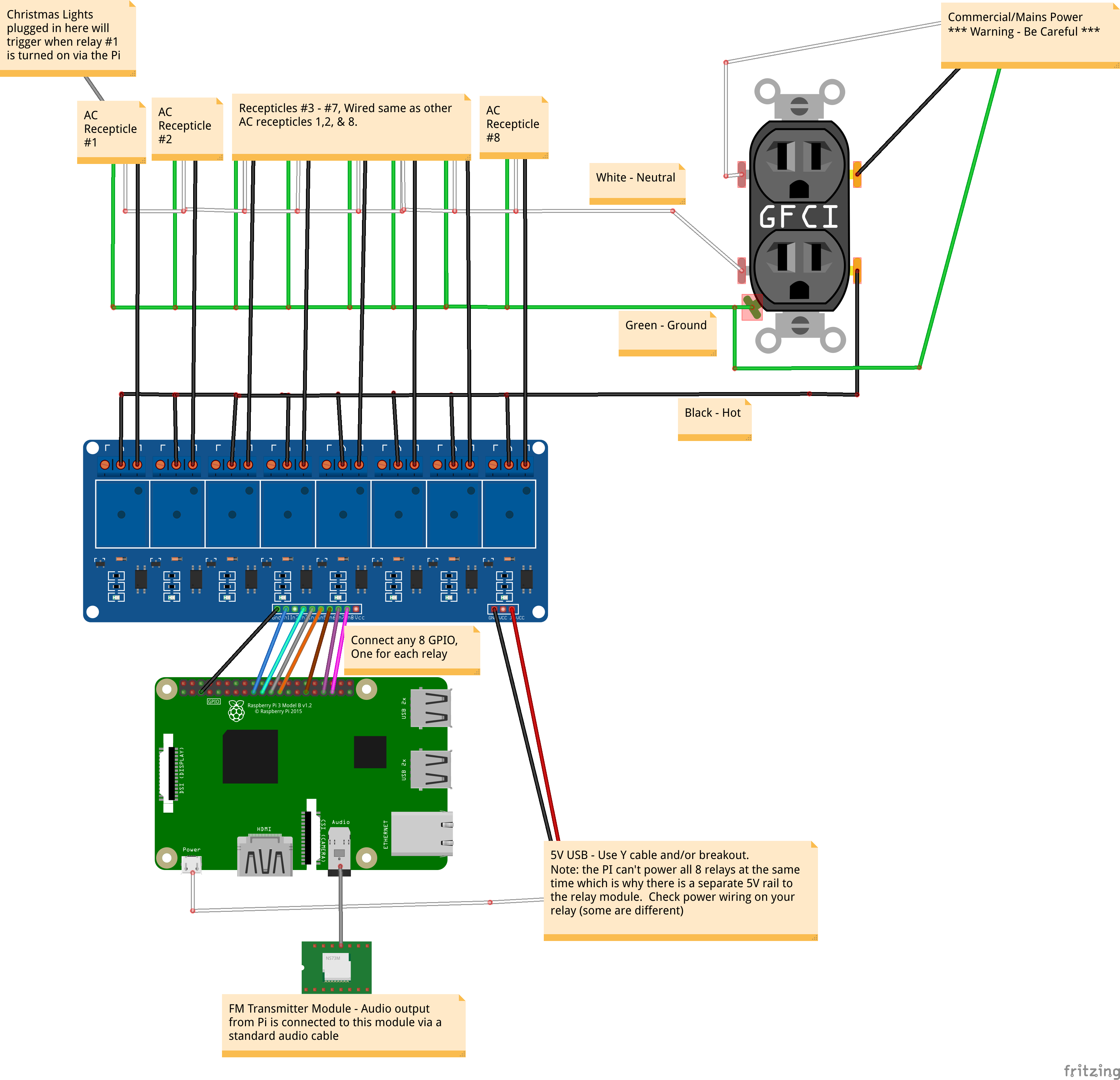
Controller AssemblyA 15ft 12AWG extension cable brings AC power into the enclosure to a 20A GFI outlet and switch combination. I wanted this protected since it would be outside. The GFI then feeds AC power to everything in the box.
I used 16 2ft NEMA extension cords, one for each relay "port", which would be turned on and off by the Raspberry Pi. Each of these extension cords would feed a string of lights.
I chopped off the ends of these 2ft extension cords to expose the black, green, and white wires and ran them through holes in the enclosure to tie to the relays and power. All Green and White wires are tied together using lever nut locks:
From the GFI, the black (Hot) wire runs through the 2x8 channel solid state relays. Then each 2ft extension cord's black wire is connected to an individual relay:
I mounted the Raspberry Pi in the box and power it from the GFI outlet, and connected it to an FM transmitter. I experimented with several FM transmitters, including directly modulating a FM signal using GPIO. I ended up using an Adafruit Trinket M0 to control an Adafruit Si4713 transmitter chip.
The PI can not reliably control the Si4713, so that is why I used a Trinket M0 I had laying around. However, I would NOT recommend this configuration. The only reason I did it was because I already had a proto-hat in use to break out the GPIO from the PI to the 16 relays, and I had the extra space...all to save an extra $15 for an external transmitter. I picked up an external transmitter from amazon later on and could have removed the Trinket and the Si4713, but opted to use it since I already built it.
In summary - Let me save you a bunch of headache and tell you that the easiest way to get an FM transmitter working is to connect the Pi's 3.5mm sound jack to an external FM transmitter and let the external transmitter handle all of the heavy lifting of generating the FM signal. The Pi is really not very good at the PWM/timing required to make it consistently work.
EnclosureI used an enclosure (12" x 12" x 6") you can find at a hardware store, e.g. Lowes.


Comments
Please log in or sign up to comment.