


Hardware components | ||||||
 |
| × | 1 | |||
| × | 1 | ||||
| × | 1 | ||||
| × | 1 | ||||
| × | 1 | ||||
| × | 1 | ||||
| × | 1 | ||||
| × | 1 | ||||
| × | 1 | ||||
Software apps and online services | ||||||
 |
| |||||
 |
| |||||
| ||||||
| ||||||
| ||||||
| ||||||
Hand tools and fabrication machines | ||||||
| ||||||
Fig 1) Demo Video:
Sentinel-Fall is a fall detection system designed to enhance safety in elderly care, healthcare, and emergency response environments. The inspiration for this system came from a real-life incident involving my aunt and uncle, both elderly individuals with diabetes. On separate occasions, they each fell in the bathroom and, though they were calling for help, no one could hear them. They were left stranded for a significant amount of time before being discovered, resulting in serious injuries. This highlighted the urgent need for a non-intrusive, privacy-safe solution to detect falls, particularly in elderly care homes where falls are a common and dangerous issue.
Unlike traditional fall detection systems that rely on cameras or wearables, Sentinel-Fall provides a non-intrusive, reliable solution that respects privacy. By utilizing 60GHz radar technology, it ensures accurate, contactless fall detection, eliminating the discomfort of wearables and the invasiveness of cameras. This approach not only guarantees privacy but also offers a more reliable solution, reducing the false positives commonly seen in traditional systems.
The ESP32-S3 serves as the system's brain, managing processing and control while sending Wi-Fi alerts. The nRF54L15 SoC enables efficient wireless BLE (Low Energy) communication, while the SIM800L GSM Module sends emergency cellular notifications. The DFRobot SEN0623 60GHz Radar Sensor offers 100-degree horizontal and vertical coverage, ensuring reliable fall detection over a wide area (up to 11 meters when mounted at 2 meters height). Additionally, the Panasonic EKMB110111 PIR Sensor is a very low-power device that remains in sleep mode until motion is detected. When a person enters the monitored area, the sensor activates and triggers the ESP32-S3 processor, which wakes up the system. The processor then activates the radar sensor for fall detection. Only if a fall is detected does the system send alerts via Wi-Fi, GSM, and BLE, ensuring optimal power usage and long battery life.
Power-saving features are integrated by keeping most components in sleep mode when not actively detecting. The carrier board acts as an IoT motherboard, housing the BLE, GSM, and Wi-Fi modules. The system uses a 7.4V Li-ion Battery, managed by the BQ25723 Battery Charger, which allows it to charge and power the system simultaneously—just like a phone. This NVDC charger ensures continuous operation while managing energy efficiently, making the system ideal for long-term, portable use without needing constant charging.
The device can be discreetly mounted on the wall for optimal coverage and operation, while remaining portable, making it easy to carry wherever needed. With smart LEDs providing visual feedback and a buzzer delivering audible alerts, Sentinel-Fall ensures immediate notifications when a fall is detected.
This non-intrusive, privacy-safe, and reliable system offers real-time fall detection, enhancing safety and providing peace of mind for families and caregivers, while effectively addressing a growing need in elderly care environments.
🔀2.0 Project FlowFig 2) Flow Chart:
Fig ) Block Diagram of the schematic:
The Sentinel-Fall block diagram presents a compact, modular architecture for intelligent fall detection. The ESP32-S3 serves as the central processor, managing system logic and sending alerts over Wi-Fi, while the nRF54L15 handles low-power BLE communication. For cellular-based emergency notifications, the system integrates the SIM800L GSM module. Fall and presence detection are performed using a combination of a 60GHz radar sensor and a low-power PIR sensor. When a fall is detected, the system delivers immediate visual and audible alerts through smart LEDs and a buzzer.
The system is powered by a 7.4V Li-ion battery, regulated through a battery charger and a power switch, producing 3.3V, 1.8V, and 5V rails for various modules. The design includes reverse battery protection in the schematic to safeguard against incorrect battery polarity.
There are three connectors
The I2C debug connector allows expansion via external I2C modules.
The nRF module connector supports drop-in use of the Holyiot nRF54L15 BLE 5.4 module if onboard connections are unavailable
The SWD J-Link connector enables programming and debugging of the nRF54L15.
To aid prototyping and testing, test points are strategically placed across key signal lines. The PCB also includes four mounting holes for secure enclosure integration.
This power estimation table shows the worst-case current consumption of the Sentinel-Fall system, measured in milliamps (mA) for each voltage rail (5V, 4V, and 3.3V). Components like the SIM800L, ESP32-S3, and nRF54L15 are listed with their peak current draw. Based on these values, power in mW and W has been calculated per rail. This data is also used to determine the minimum PCB trace widths during layout, ensuring safe current handling without overheating or voltage drops. The green cells represent current values, aiding in accurate power draw.
🟩 3.2 PCB Design & & Layout Considerations.To ensure robust electrical and thermal performance, all power rail widths were calculated using Saturn PCB Toolkit. Based on worst-case current consumption, a 30 mil trace width was chosen for all major power lines. This keeps the voltage drop under 0.1V and avoids overheating, even under loads of up to 3A, using 1 oz copper. For high-current paths and rail transitions, multiple 12–24 vias , with each via capable of handling approximately 1.4A, ensuring adequate current density and minimal resistance. At least 2–3 vias are used for each power transition.
Signal integrity and routing practices were carefully follow
- USB DP and DN traces are routed with W = 2H spacing for 50 Ω impedance, using 3W spacing for loose coupling.
- All I2C lines are routed with >2W spacing from adjacent digital signals to minimize crosstalk.
- The crystal oscillator is placed as close as possible to the MCU, maintaining >20 mil clearance from other traces.
- Decoupling capacitors are placed directly adjacent to power pins for effective high-frequency filtering.
- A continuous return path is maintained for all USB signals, with reference vias added for every 4 GPIOs to ensure signal integrit
- For mechanical clarity and easier assembly, silkscreen labels are added for all connectors, including pin numbers or shorthand signal names. This is critical for avoiding confusion during PCB assembly and ensuring accurate manual or automated component placement.
The Sentinel-Fall PCB measures 60 mm × 85.16 mm and is built on a 4-layer stackup to ensure signal integrity and robust power distribution. The layer configuration includes L1 – Top (signals/components), L2 – dedicated GND plane, L3 – power plane with ground stitching, and L4 – Bottom (routing and components). This structure allows for clean signal routing, reduced EMI, and Enhanced Signal Integrity.
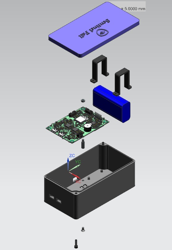
This 3D-printed enclosure (Modeled using Autodesk Fusion 360) is purpose-built for wall mounting and features a two-part design consisting of a top lid and bottom lid for easy access and assembly. Made from PLA plastic and printed using a Prusa MK4, it has a sturdy 2.5 mm wall thickness that offers both durability and a clean finish. Inside, two mounting brackets are included to securely house the battery. Precise cutouts are provided for the PIR sensor, status LEDs, DIP switches, and the main power switch. The PCB is fastened firmly against the housing using screws, nuts, and spacers to ensure stability. The enclosure is dimensioned to fit perfectly with a phone holder wall-mount like this model, making installation quick and secure in bathroom or elderly care environments.
</> 3.4 Firmware Architecture -ESP32 Code:
The ESP32-S3 acts as the central controller of the Sentinel-Fall system, managing operations based on sensor inputs and DIP switch configurations. It starts in deep sleep mode to conserve power and is awakened by a signal from the PIR sensor when motion is detected. Once active, it enables the 5V power rail, starts a Wi-Fi hotspot, and initiates a 5-minute monitoring cycle using input from the 60GHz radar sensor. If a fall or presence is detected during this interval, the ESP32 reads the DIP switch status to determine which alert mechanisms to trigger.
- Depending on the configuration, it can:
- Send a high signal to the nRF module to trigger BLE terminal alerts,
- Initiate email alerts over Wi-Fi,
- Enable the 4V rail to power the GSM module for SMS or call-based alerts, and
- Activate LEDs and a buzzer for immediate local feedback.
b) nRF54L15 Code :
The nRF54L15 firmware is lightweight and dedicated to one primary function: pin (P1.06) from the ESP32—marked as the " ESP_NRF_GPIO1_BLEALERT" in the schematic. When this pin goes high, indicating that a fall has been detected and a BLE alert is requested, the nRF module immediately sends a corresponding BLE status message to a paired device (e.g., a mobile app or terminal example nrf connect).
c) Demo Video using NRF DevKit
This demo shows the nRF54L15 Development Kit sending switch button status over Bluetooth Low Energy (BLE) to the nRF Connect mobile app.
We transmit a simple payload whenever the switch state changes and also monitor the RSSI (Received Signal Strength Indicator) to track signal strength and proximity.
This forms part of the Sentinel Fall system’s low-power communication framework using BLE.
📦 4.0 Component Selection1) C1001 60GHz mmWave Sensor
The C1001 60GHz mmWave sensor was selected after extensive research as it stands out as one of the most advanced options currently available in the market. It offers an excellent balance of long detection range (up to 11 meters for movement and 5 meters for fall/static), wide 100° detection angle, and high accuracy in fall detection using point cloud data. Its optimized power consumption (~90–100 mA) makes it suitable for always-on applications. Most importantly, its robust fall detection algorithm provides reliable performance in real-world indoor environments, making it ideal for critical safety systems like Sentinel Fall.
2) PIR Sensor: EKMB1101111
This PIR sensor was chosen because it comes as a complete, self-contained module enclosed in a durable plastic housing. Unlike raw PIR elements, this sensor includes all essential internal circuitry such as a built-in amplifier, comparator, and signal processing components, significantly simplifying integration. It ensures high reliability, EMI resistance, and minimal external components—ideal for compact, low-power embedded systems like Sentinel Fall.
3) Microcontrollers & Communication Modules:
The ESP32-S3 MINI-1 N8 was chosen for its compact form factor, integrated PCB antenna, and improved capabilities over the earlier ESP32-S2. The nRF54L15-QFAA-R is Nordic's newest ultra-low-power BLE SoC, ideal for always-on wakeup and BLE pairing with minimal energy use. Its inclusion was also a requirement of the "Kitchen Sink Award", which mandates using this specific chip. Since it lacks Wi-Fi, the ESP32 was essential for full IoT connectivity. Lastly, the SIM800L, while a legacy GSM module, was selected for its widespread adoption, available libraries, and ease of integration—making it ideal for rapid development and reliable SMS alerts in resource-constrained environments.
4) Battery Charger: BQ25886RGER
The BQ25886RGER was selected for its NVDC buck-boost architecture and integrated PowerPath feature, enabling seamless switching between battery and external input without interrupting system operation. It is programming-free, with key parameters like charging current easily configured via external resistors. Its compact design and dual power management role make it ideal for space-constrained, battery-powered applications like Sentinel Fall. Note: It does not include over-discharge protection, so it is essential to use a battery with built-in BMS (Battery Management System) for safe operation.
5) Regulators: MYLSM00502ERPL + MCP1727-3302ESN
MYLSM00502ERPL was chosen because it's a compact buck converter with an internal inductor, simplifying layout and reducing external components. The MCP1727-3302ESN is a fixed 3.3V low-dropout regulator, selected for its stability and low quiescent current
🔧💻🔨 5.0 Assembly, Programming & Testing prcodeure :⚙️Step 1: PCB Fabrication & Assembly with PCBWay:To initiate fabrication, upload the following files to PCBWay:
Gerber files, Assembly file ,BOM (Bill of Materials) and Pick-and-Place file All required files are provided at the end of this article. Next, select the PCB settings exactly as shown in the provided reference images.
Place the order for both PCB manufacturing and PCB assembly together through PCBWay.
⚙️Step 2 : Firmware Programming – ESP32 & nRF54L15:ESP32 Programming:
To program the ESP32 you will need the USB to ttl converter Connect the GND RX and TX between the Board and the USB to TTL
Follow the following steps if ESP32 is not present in arduino as board
- Open Arduino Goto Files>Preferences
- In the Preferences window add the following link in the Additional Boards Manager URLs https://raw.githubusercontent.com/espressif/arduino-esp32/gh-pages/package_esp32_index.json
- Then Goto Tool > Board > Board Manager
- In the new window in search bar search esp32 and install esp32 by Espressif Systems
- Open the .ino file in the arduino then Tool > Board >ESP32 and select ESP32S3 Dev Module
- Now press the reset button, press the Boot button, release the reset button and then release the boot button
- The esp32 is in boot mode now you can upload the code via arduino by clicking the upload button or goto Sketch and UPLOAD.
nRF54L15 Programming:
The nRF54l15 SoC programming can be done by using a 10-pin connector from the Debug Out Pins from a nRF54L15 DK and connecting it to your custom board. More information can be found in this thread, Subject: Inquiry: nRF54L15 DK Schematics & Programming Options - Nordic Q&A - Nordic DevZone - Nordic DevZone
We Can use this method to flash our nRF SoC as shown in the above picture. Alternatively, a Segger J-Link programmer can also be connected instead of the nRF DK and can be used to flash the SoC in the same way (SEGGER announces support for Nordic Semiconductor nRF54L15 Cortex-M33 with RISC-V coprocessor)
However, even without a programmer or a DK, the nRF SoC can be programmed directly using an ESP32 through the SWD Pins. This involves bitbanging the swd commands from the ESP 32 GPIO Pins. A useful reference for this is ESP32 Turned Handy SWD Flasher For NRF52 Chips | Hackaday
To program the nRF54L15 DK/SoC, we used the nRF Connect VS Code Extension. This extension has all the required tools to flash the board, including the Application and Action windows and sample starting code for your projects.
We started with the Peripheral UART Code and integrated the GPIO level checking and custom message transmission into this code for this project.
Once the program is completed, we can use the Flash option in the Actions window to program the board. This option automatically generates the hex file to flash, erases the existing firmware on the board and programs our new code onto the board.
Once the code is flashed, we use the nRF Connect for Mobile application to connect to the “Nordic_UART_Service” bluetooth connection OR "Sentinel Fall" for actual Product. Then, we enabled the TX Characteristics with the UTF-8 mode so that both numbers and text are visible. Once this is done, we can see the BLE Alerts in the Terminal section every time the GPIO status of the monitoring pin goes high.
⚙️Step 3 : Hardware Integration & Enclosure Assembly:- 3D print the enclosure:
Use a 3D printer (e.g., Prusa MK4) to fabricate the enclosure parts based on the provided STL or STEP files.
- Securing PCB with Spacers & Nuts
First, place spacers, insert the PCB into the mounting holes, and fix it using nuts. On the other side, secure the PCB tightly to the case using M3 flat head screws. Finally, connect the battery to the JST 2P connector on the board.
- Secure the battery:
Place the mounting brackets, insert the battery, and screw them in with M2.5 flat head screws, tightening them with hex nuts.
- Fastening PCB to Bottom Lid with M3 Screws
First, place spacers, insert the PCB into the mounting holes, and fix it using nuts.
The fully assembled device was mounted onto an adjustable phone holder for final deployment. The mount should be positioned horizontally, facing downward, at a height of 2–3 meters—ideally in locations where a person is likely to fall or get injured. Alternatively, the device can also be mounted at a slight angle, depending on the coverage area required.
Set all DIP switch toggles downward to turn them ON. Slide the power switch to the left to power on the device.
BLE: Pair Device with mobile app
GSM: :Modify the phoneNumber variable in the code, or enter your phone number directly through the ESP32 web server at 192.168.4.1 by connecting to its hotspot.
Email Configuration: To send an email using the ESP32, you’ll need to configure your email account by following these steps:
- Enable 2-Factor Authentication on your email account to allow secure app-specific access.
- Go to your account’s App Passwords section (e.g., Google App Passwords), enter a name like ESP32, and click Create.
- A 16-character password will be generated—copy and save it, as you’ll need it in your ESP32 code for email authentication.
⚙️Step 7 : Demo Video
- 🎥 Sentinel-Fall Functional Prototype Demo
Demonstrates the full system in action using development kits, showcasing human presence detection and Wi-Fi-based alerts.
- 📲 Bluetooth Alert Demo (nRF54L15 Dev Kit)
Shows BLE-based alerting functionality using the nRF54L15 development board. A switch payload status (ON/OFF) is sent to a BLE terminal to simulate alert triggering.
- 📡 C1001 Sensor Standalone Demo
Demonstrates the C1001 mmWave sensor’s ability to detect human presence. The onboard LED lights up when a person is in range and turns off when they are out of range.
(For Murphy's law survivor award consideration)
3D Casing Revisions:
The first enclosure had dimensional inaccuracies and did not fit properly into the phone holder. The second version fit correctly but had poor visibility for the DIP switch, USB port, and power switch engravings. The latest revision improved engraving clarity; however, external stickers will be added for the DIP switch, USB, and power switch Stickers, as the engravings are still not sufficiently visible.
Fall Sensor Troubleshooting:
Fall detection was initially unreliable. Several adjustments were made after discussions with DFRobot support to optimize radar sensitivity and sensor positioning. DFRobot has also followed up via email, telling they would do a library update to improve performance. Additionally, the Seed Studio fall sensor is currently out of stock if wnat to try different sensors. (Support forum: https://www.dfrobot.com/forum/topic/356347)
ESP32 Chip Failure & Replacement Plan: The ESP32 chip appears to be corrupted. Upon powering the board and switching it on, we measured 8V input on the multimeter. However, when connecting the USB-to-UART debugger, the ESP32 was not detected. We verified the reset and boot switches for continuity, and they were functioning correctly. The ESP32 is receiving 3.3V, but we're unable to measure 4V or 5V, as these are typically enabled by the ESP32 itself.ESP32 Chip Failure & Replacement Plan
Additionally, during final testing on the day of the submission deadline, the 5V line and one of the input pins got shorted, which unfortunately damaged the nRF development kit. However, this issue occurred after we had successfully recorded the initial BLE alert demo, where a push-button switch on the development kit was used to simulate a fall, and alerts were sent to a terminal app. While this setback prevented further testing and refinement, the core BLE functionality was successfully demonstrated and captured earlier.
Based on our diagnosis, the chip is likely damaged—possibly due to the use of low-cost alternative components during a rushed production phase. As a result, the project is currently incomplete. We plan to desolder the faulty ESP32 and replace it with a new one, so stay tuned for updates!!
Project Timeline Update
Our PCB, expected by April 26th, arrived on May 1st, which delayed final integration and testing. This, combined with finals week for three of us at the University of Colorado Boulder, made it challenging to stay on schedule during the final stretch.
Planned Improvements for Future Revisions:- BLE Controller Shift: Future versions could use the nRF54L15 as the main controller, relegating ESP32 to Wi-Fi only, or move to a Nordic Wi-Fi+BLE SoC.
- Cheaper PIR Sensor: Replace the current $10 PIR with a $3 module enclosed in a custom 3D casing.
- Grounding Isolation: Separate chassis ground from PCB ground to protect against ESD from screw contacts.
- Heat-Set Inserts: Add brass inserts in top and bottom holes for stronger, reusable screw mounting as PLA is brittle.
📦 PCB Assembly and Manufacturing Files
Contains Gerber files, pick-and-place data, and other necessary files for fabrication and assembly.
📘 Design Documentation
Includes system architecture, design rationale, firmware overview, and testing procedures.
🧾 Schematics
Electrical circuit diagrams in standard SCH format for reference and editing.
📋 BOM (Mechanical + PCB)
A complete Bill of Materials listing all mechanical and electronic components used.
🧱 3D Files (Top Lid, Bottom Lid, Mounting Brackets)
STL and STEP files for 3D-printing the enclosure and internal mounts.


_t9PF3orMPd.png?auto=compress%2Cformat&w=40&h=40&fit=fillmax&bg=fff&dpr=2)


Comments
Please log in or sign up to comment.