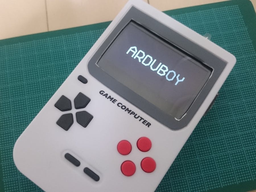
In 2019, I found an article about "Pocket Game Computer" and I thought that this device can be remodeled as an Arduboy clone.
Fortunately I could buy this device, but currently it's hard to get this one, I think...
Disassemble "Pocket Game Computer"It seemed that buttons, speaker, battery case, and power switch could be reused.
I divided the main board into 3 pieces.
The left part was reused as controller board and the right part was reused as power switch. The middle part wasn't necessary so it was thrown into a garbage b box.
Controller BoardThere were D-pad buttons, reset button, start button, sound button, A button, and B button. It looked that there were 4 buttons for right hand but they were 2 sets of common 2 buttons actually.
I scraped the surface of the board a little and soldered wires directly.
A 1x10 pin header was soldered on the opposite side.
Caution: The labels A and B in this picture are based on Arduboy definition. The silks on the board are B for left side, A for right side, but the wire from left side must be connected to the A pin and the wire from right side must be connected to B pin.
SpeakerI removed the original wires and soldered a 1x2 pin header directly.
I bought a 2.54 inch OLED display. It was lucky that this display could fit into the housing though I didn't know its size.
I soldered a 1x7 pin header and bent these pins to connect a socket horizontally.
Caution: The driver of this display is SSD1309, isn't SSD1306 which is normal Arduboy's. Therefore it is necessary to edit the source code: "core.cpp" of Arduboy library or "Arduboy2Core.cpp" of Arduboy2 library to control the display correctly.
// Display On
   0xAF,

+  // Set Page 0, Column 0 as Start Address
+  0xB0, 0x00, 0x10,
+
   // set display mode = horizontal addressing mode (0x00)
0x20, 0x00,I created mini circuit board for a RGB LED. I used a 150 ohm resistor for red, a 240 ohm resistor for green, and a 91 ohm resistor for blue. (You don't have to use these resistors as exactly same as mine. About 220 ohm is well.) A 1x4 pin header was also soldered.
I soldered wires at the soldered points of the power switch. A 1x2 pin socket was soldered on the opposite side.
The window of screen was extended. I made holes to put out the USB connector of the Arduino Micro and the RGB LED.
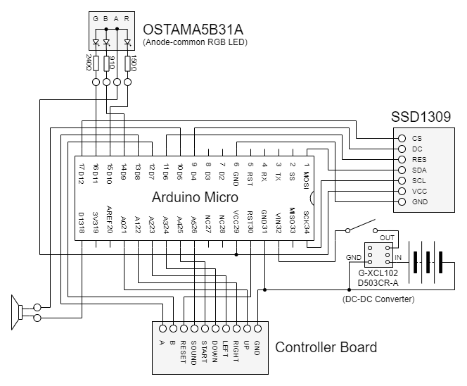
I soldered wires, pin sockets, and so on to the Arduino Micro according to the schematic, and connected peripherals. I fixed the Arduino Micro and the RGB LED by a glue gun.
Actually, I inserted a DC-DC converter for stable power supply (but it isn't shown in this photo).
Then I closed the housing. It was completed.
Thank you for reading my article!


_PnKPri8a6q.jpg?auto=compress%2Cformat&w=48&h=48&fit=fill&bg=ffffff)


Comments
Please log in or sign up to comment.