The imaeis the sae
SparkFun handed out soldering kits at an event I attended last October. Recently they announced a contest to modify that kit. I submitted this to them, but I still wanted to share with my Hackster friends. After three agonizing weeks of waiting for the results, I won.
https://www.sparkfun.com/news/2082
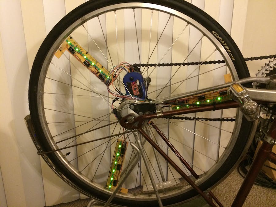
What is a Badger POV?Persistence Of Vision uses carefully timed flashes of light to create the illusion of a complete image. I used three arrays of 24 LED that flash at a certain position in a bicycle wheel's rotation to create images. Three arrays allow the device to operate at slower speeds and still generate an image.
SparkFun makes a giveaway kit for events where they teach people to solder. It includes a battery pack, some connectors, a 7x8 array of LEDs and a microcontroller board that resembles an Arduino. The kit assembles into a name badge called the Badger.
Housing the BadgerI bought a cheap flash light intending to harvest the 27 white LEDs from it and discard the rest. However, the housing was perfect for this project. It has a battery holder with 3 AAA batteries, a power switch, and a window to show I actually used the badger.
I started by removing the LEDs. Three in front just slid out and I desoldered the wires. The main board contains an array of 24 LEDs and a power switch. I scored the board with a craft knife and carefully broke it along that line to separate those two sections.
While trying different positions of the Badger inside the case, I realized the USB connector can orient towards the opening. Great news! I don't have to undo 8 tiny screws to program the microcontroller. The housing doesn't have screws and holes that work with the badger, so I made a mounting bracket. It lifts the end of the badger at an angle that allows a USB extension cable to connect through the opening on the end.
New problem: in that orientation, the through-hole leads of the power switch rub against the other circuitry on the Badger. Since the power switch board is copper clad on only one side, I just flipped it over and left the switch on top. The three legs are placed symmetrically, alignment is easy. I bent the leads up to convert the switch to SMD, and mounted the power board back in the housing.
The last part inside the housing was wires. My jumper wires have a plastic shroud over the crimped connector. That connector is too long once inserted into the female pin headers on the side of the Badger. I removed the plastic and replaced it with heat shrink tubing. That allowed the pliable crimp-on ends to bend within the confines of the case.
Display SpokesThree "spokes" allow the display to persist at a reasonably low speed. One source claims a single spoke requires 25 mph to create a full image.
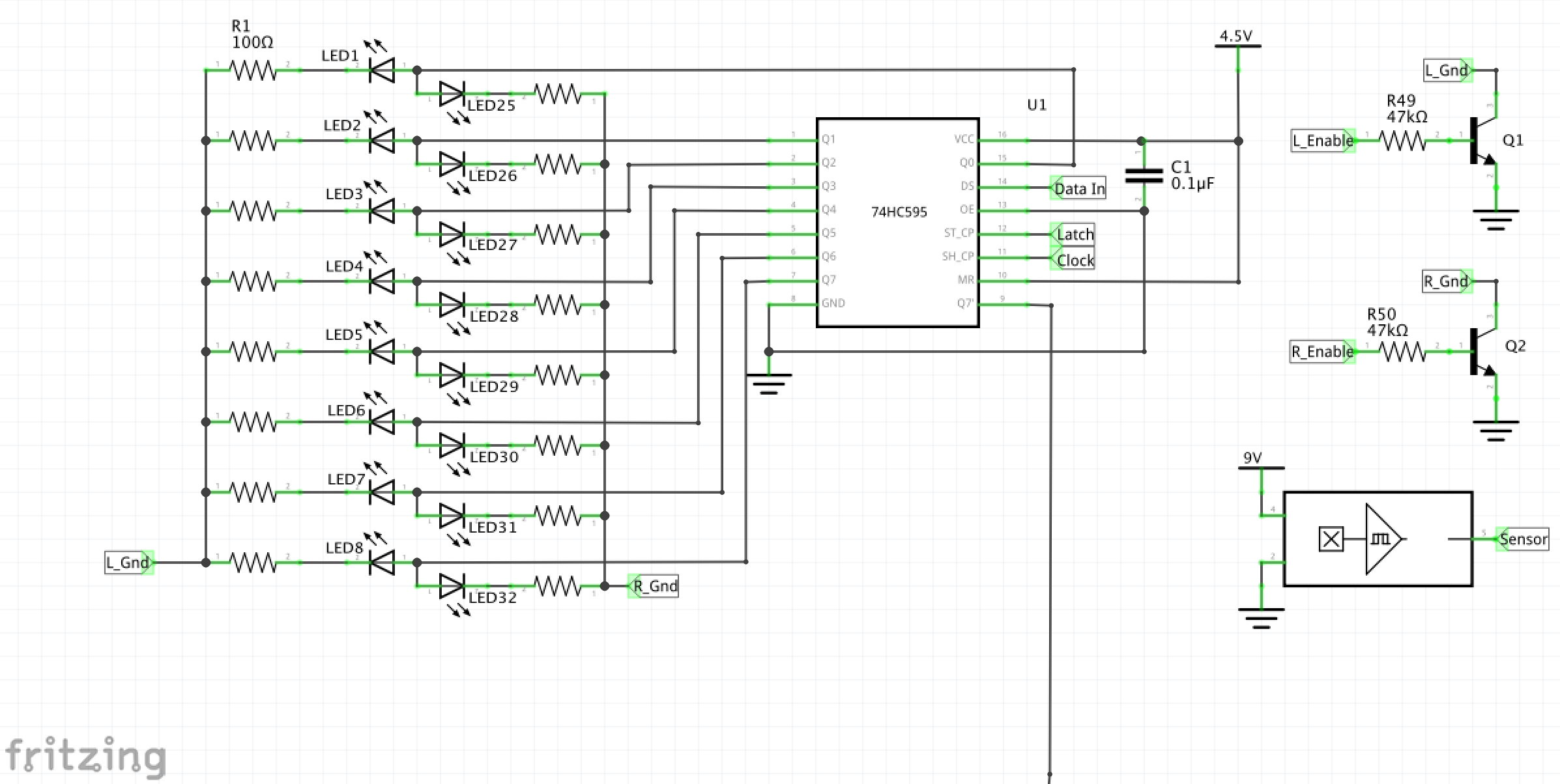
Each spoke is modular and functionally identical. That way they can connect in any order without worry of affecting operation. The male pin headers have a row for input and another for output for to complete the circuit across all 3 spokes. Each spoke has 1 hall effect sensor, 3 shift registers, 6 bussed resistors, 2 transistors, and 48 LEDs.
Output CircuitsThe badger used 8 pins to operate a 7x8 array of LED using a technique called charlieplexing. (see my previous Hackster.io project: The Charlie Chaser) Charlieplexing, however, is the wrong technology for this project. The off time between flashes would make image artifacts and ruin the effect. Shift registers were the obvious choice for the required 72 outputs (24 LEDs * 3 spokes). A shift register collects all the data it needs and simultaneously changes the parallel outputs. That gives the image much more stability. This YouTube video does a FANTASTIC job explaining how they operate.
Each of the 72 outputs has 2 LEDs connected for a total of 144. Each side of the spoke has a it's own ground connected to a transistor controlled by the Badger. Isolating the two sides allows non-symmetrical images on only one side of the wheel; specifically text.
The original scope of the project included displaying letters on the top half of the wheel to the left side and on the bottom of the right side. With the top right and bottom left disabled, the text could display correctly. Experimentation showed the device (or maybe the code) is too slow to make more than 24 frames in a single rotation. Therefore, text fell off of the backlog.
Input CircuitsSo many of the digital I/O pins are used for output that the analog inputs are used to read digital inputs. The hall effect sensors in this project are monopole, non-latching. Given sufficient magnetic flux density of a south pole, the output pin changes from high impedance to digital low. Fortunately, the analog inputs of the atmega328 have input pull up resistors.
The power switch is single pole double throw, but with a twist. It's a latching push button that latches open between toggling to each connection: off -> pole A -> off -> pole B.
Code CommentaryCoding was the most stressful part because I did most of it in 3 days. I underestimated how long it takes to solder 144 LEDs, tiny wires, and resistors.
Goals
Goal 1: display a static image
Goal 2: display animation
Goal 3: display text
Goal 4: acquire configuration from wireless device
The only goal I reached is one. The finished product could still include goals 2 and 4, but time did not allow.
Paradigm
I started writing this as a functional program, but it quickly got too long to manage. Switching it to an object oriented program was primarily to maintain some sanity.
There are three classes
- POV: represents the whole of the hardware
- Spoke: setup for relevant outputs and sensor read functions
- Image: sets and gets all image data
Frames and FrameGroups
The image is divided into 24 frames. Each frame is 3 bytes of data displayed for X° of rotation, where X is 360/Frames. The framegroup is the quantity of frames between two evenly placed sensors. These numbers are set by some preprocessor variables for flexibility. While experimenting, the FRAMES variable let me quickly dial in the most effective number of frames without searching through my code for all the frame and framegroup quantities.
Added bonus: if one of my spokes breaks, the SPOKES variable can adjust down to make the whole device work with almost no recoding.
#define FRAMES 24
#define SPOKES 3
#define FRAME_GROUP (FRAMES/SPOKES)
Sensors
On this project I learned digital writing to an analog pin will enable/disable the pull-up resistor in the Arduino library:
digitalWrite(sensorPin, HIGH);
In the spoke constructor, the digitalWrite() function sets the internal pull-up resistor on the analog input. The POV object picks a sensor to check and ignores the others. When a spoke's readSensor() function is called, it compares the analogRead() value to 512. This simulates digital reading on an analog input.
if(analogRead(sensor) < 512)
	{
		return true;
	}
	else
	{
		return false;
	}
Time
To meet goal 1, I wanted everything running as fast as possible it wouldn't miss a sensor reading because. Instead of using the delay function I followed the blink without delay pattern to set the duration of each image and each frame. I expected to have 120 frames at a max of 4 revolutions per second. That would be pretty fast down a hill.
1000 / 4 * 120 = 2.083ms per frame
If that slows down to 3 RPS:
1000 / 3 * 120 = 2.778ms per frame
2 RPS yields 4.167ms and 1 yields 8.333ms. These numbers indicate milliseconds would be too imprecise at higher speeds to make the desired image. The time functions all use microseconds instead.
Shift Register Support
The existing code I saw for shift registers would send one byte and then latch. This project requires nine bytes before the latch. I borrowed heavily from the Arduino Shift Out tutorial.
After talking with a friend that is more experienced with microcontrollers and Shawn Hymel, I made a couple of updates. They convinced me further the 4Mhz clock speed is the bottleneck this project suffers from. Also, the analogRead() funciton is more time consuming than digitalRead(). I decided to scrap the reservation of digital pins for wifi. The hall effect sensors now connect to those digital GPIO lines. I also tried using interrupts to activate the update functions.
Testing
Did I gain anything? I got the frame count up to 36! Compared to 24 it jitters more, but all things considered, I call that a plus.
Interrupts would be an awesome replacement for checking the pins in every loop. I think it might save a huge amount of time. Unfortunately, that idea never got off the ground. :( Any "Arduino" using a ATMega328 can only have interrupts on pins 2 and/or 3. ( Source: Arduino AttachInterrupt) Since I need 3 interrupts, I didn't bother changing pins around.
Here are some pictures of my testing. I noted the number of frames in the firmware and the shutter speed of the camera for the photo.
The picture below is what I hoped to see when the weel spun, but that was not the case. This is a little over one rotation. The overlap areas are the three slightly brighter regions where the misalignment is evident. It looked cool in short bursts, but the overall effect was not POV.
Here are the same device settings with a longer shutter.
The image below has terrible alignment in the overlapping regions. I count 16 frames in a frame group, so I think this was an attempt at 48 frames.
In the end I settled on this. Some drift is noticable, but for this little bit over the course of a whole second, I'm content.


_3u05Tpwasz.png?auto=compress%2Cformat&w=40&h=40&fit=fillmax&bg=fff&dpr=2)


Comments
Please log in or sign up to comment.