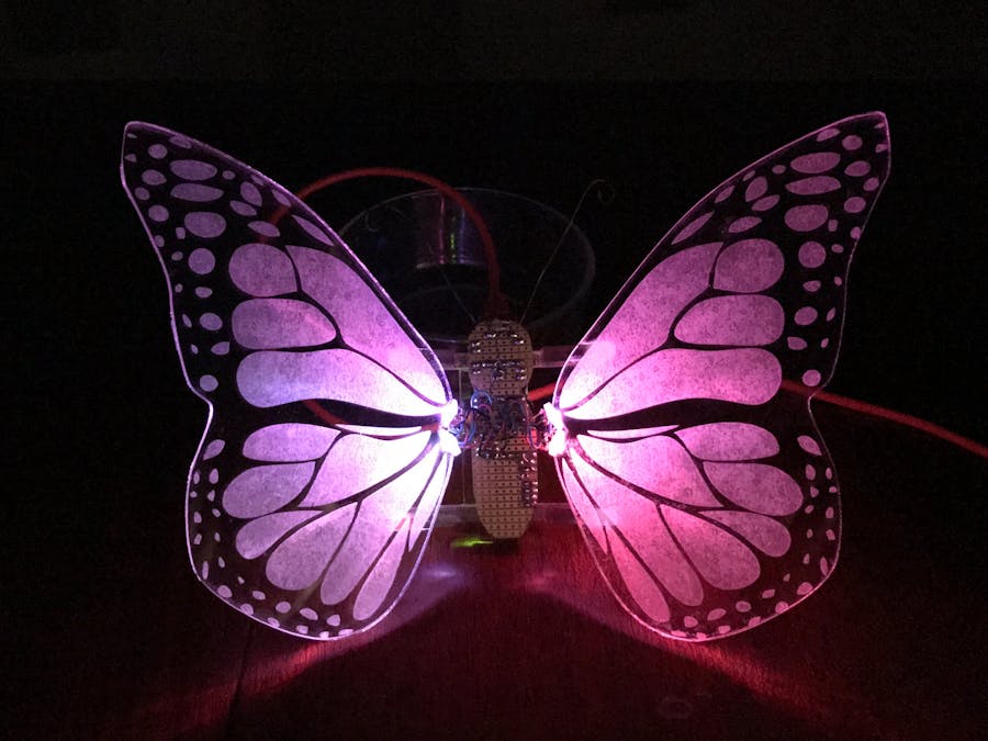
My wife asked me, "Do you mind if I spend $27 on a toddler alarm clock?" When I figured out what such an alarm clock does, I decided I could make that from parts I had in my pile.
WingsSince I have access to a laser cutter at work, I got some 1/4" acrylic and cut/etched the wings. The design came from pixabay and has a creative commons license. https://pixabay.com/en/animal-butterfly-design-insect-1297939/
I took one wing, created a vector outline for the cut and copied it for the second wing. That's why these don't exactly match the image linked above.
LightsI played around withe the RGB LEDs to try and find an orientation I liked. It seems the edge of the acrylic deflects light perpendicular to its surface. I had to modify the wings with the angular notch to get the light all the way out to the wing tips.
The LEDs are through-hole, but I glued them to the wings instead of a PCB. With the legs sticking out, I soldered wires to them for easier connection to the body when the time came.
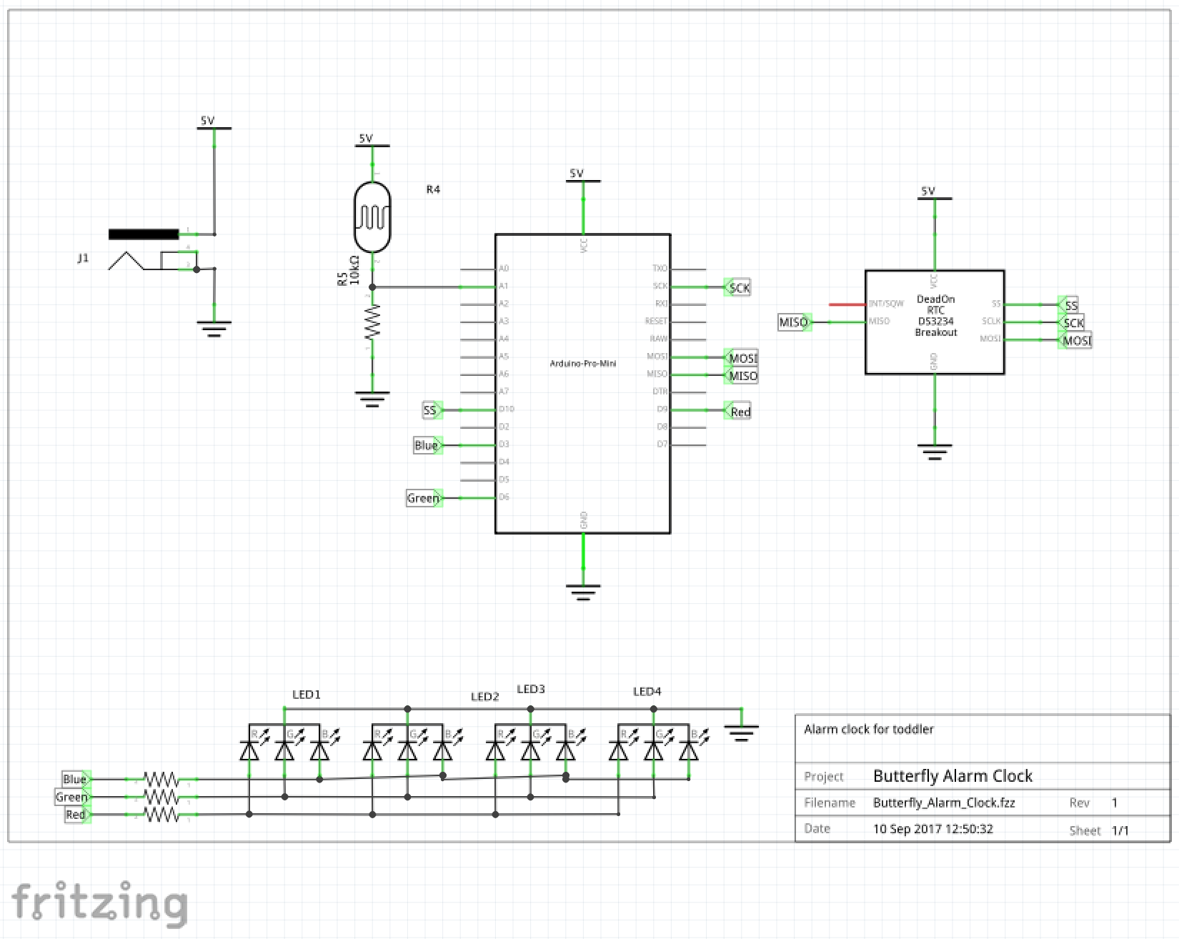
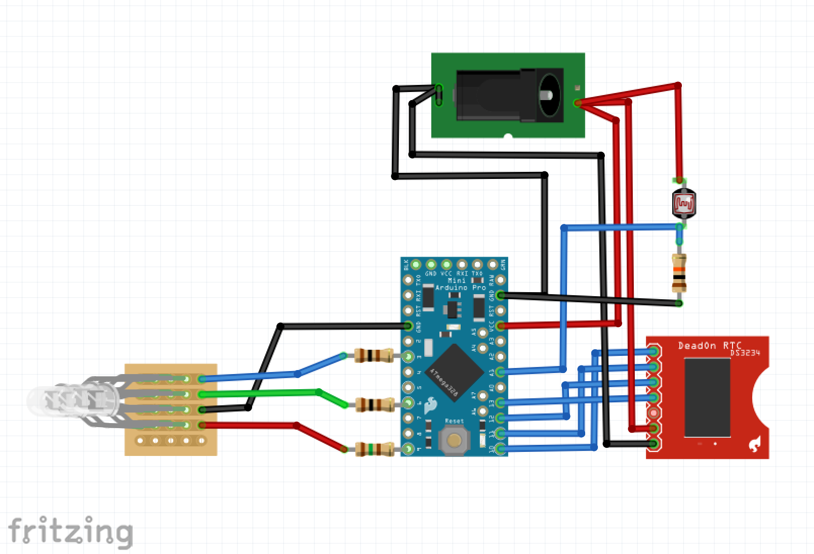
BodyI want this to be more than just wings. It must be a butterfly. The body has a microcontroller and the real time clock. The proto-board has its traces sideways because there was less trace cutting that way.
The Arduino is in the head and the RTC is in the abdomen. The thorax is a busy place with interconnecting wires, the barrel jack for power, and the connection points for the wing LEDs. All of those small things needed to be in place before the larger boards were soldered on top. Not all the solder points on the boards have pins. The included pins are either functional or mechanically supportive.
The photoresistor's purpose is to adjust the wing brightness to the room brightness. It sits on the top of the head to face into the room where it's mounted.
I kinda made this up as I went. The two telephone shaped spars hold the wings at about 120 degrees apart. One rib sits between them to hole them parallel and provide a wall mounting surface. Programming a pro mini is done with an external FTDI cable. The pins for that are exposed outside of the base.
The base and wings hold together with super-glue. After assembly, I realized the trough in the middle wasn't deep enough for the electronics. I wanted to make this as anatomically correct as practical, but the wings are on the side of the thorax instead of the top. Sorry, entomologists. Next time I'll take some measurements instead of... winging it.
My code didn't check the timer correctly, but that won't be too hard to fix. I'll update that in the project logs. It does however, set the time correctly. Programming the settings is done over the save FTDI cable as flashing the firmware. Just open the serial terminal with 9600 8-N-1 and press "?" for the menu. The settings are stored in the flash of the RTC.
Update: code is fixed. The lights turn on and off at the correct times.


_3u05Tpwasz.png?auto=compress%2Cformat&w=40&h=40&fit=fillmax&bg=fff&dpr=2)
Comments
Please log in or sign up to comment.