I needed a temperature and humidity sensor that would show maximum and minimum levels recorded so that I could monitor the levels in my greenhouse. I do not have any power in the greenhouse so the aim was to reduce power consumption as much as possible so that it could run on a rechargeable battery for long periods.
The solution to this was to have the Arduino enter a low power state for a period before waking and taking new reading then repeating the cycle. To achieve this I used the rocketscream low power library to put the processor to sleep, waking every 24 seconds to check the temperature and humidity, which takes less than a second.
(NOTE: I have created a variation of this project Temp and Humidity Monitor with Graphs and Battery Monitor which you may also like to check out. Does not use power saving but the battery still lasts 5 days and the battery monitor lets you know when it needs recharging.)
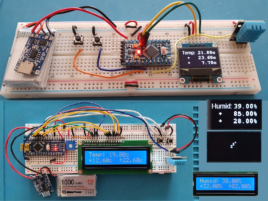
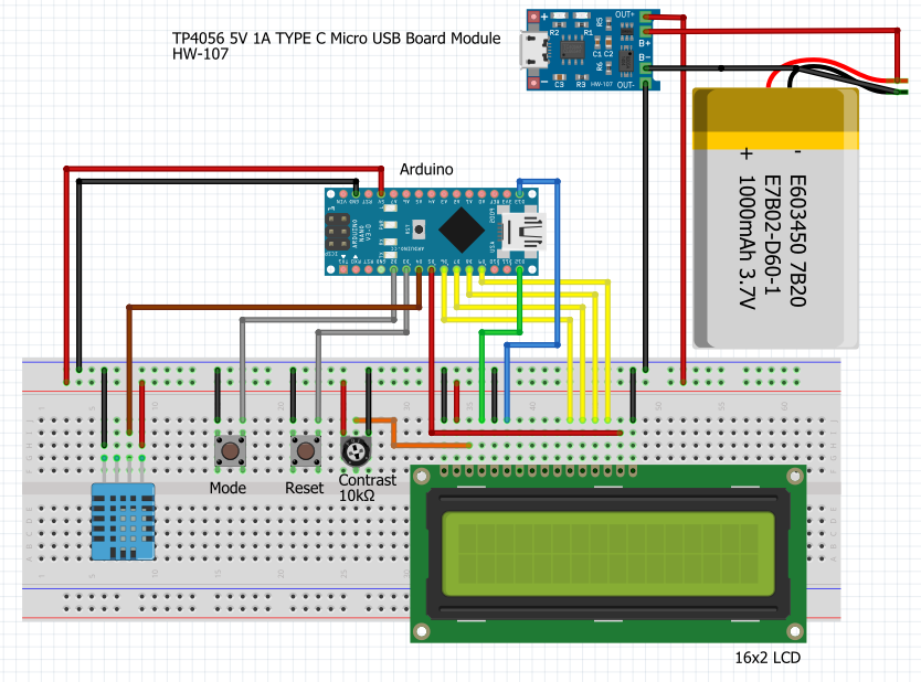
My first version used an Ardino Nano R3 with a 16x2 backlit LCD display. This worked well and power consumption was as follows:
Asleep:                               24 seconds    5.6mA
    Checking temp./humid. between sleeps  <1 second     14mA
                                          So on average 6.0mA
    With backlight on                                   28.5mA
Using a 1, 000 mAh rechargeable battery the system should last for up to 7 days between charges – frequently turning on the backlight will obviously reduce this. In fact my version has been running for over 8 days and is still operational.
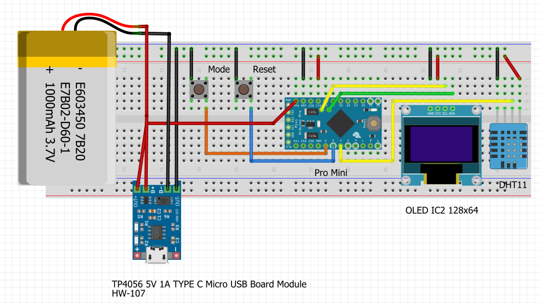
The second version used an Arduino Pro Mini with an OLED 128*64 display. The display does not need a backlight and is easier to read in bright daylight. The power consumption of this was:
Asleep:                               24 seconds    3.23mA
    Checking temp./humid. between sleeps  <1 second     6.8mA
                                          So on average 3.4mA
    Awake - displaying
Using a 1, 000 mAh rechargeable battery the system should last for up to 12 days between charges – frequently turning on the display will reduce this, but it is low consumption so should not be noticeable.
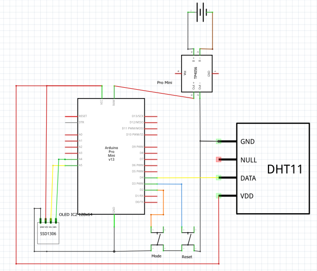
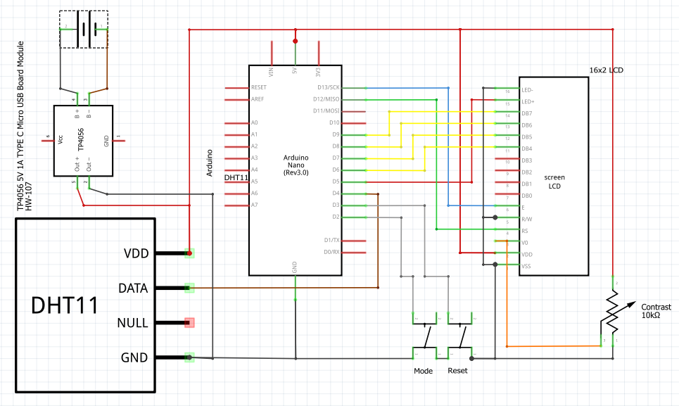
I have included schematics and code for both versions. Either version should run on most Arduinos.
The code (OLED version)The code uses the following libraries:
#include <DHT.h>            // This is the DHT sensor library by Adafruit
	#include "LowPower.h"       // Low-Power library from rocketscream
		  		     // required for the OLED display
	#include <SPI.h>            // Synchronous serial data protocol library
	#include <Wire.h>           // IC2 communications library
	#include <Adafruit_GFX.h>   // Adafruit Graphics Core Library
	#include <Adafruit_SSD1306.h>  // SSD1306 library for Monochrome 128x64 and 128x32 OLEDs
And these fonts from the Adafruit Graphics Core Library:
#include <Fonts/FreeMonoBold9pt7b.h>
	#include <Fonts/FreeSans9pt7b.h>
The main areas of interest in the code is the the loop() which puts the processor to sleep.
// Check to see if has been awake for the keepAwakeFor period
 // if so allow to go to sleep
 if ((millis() - timeWoken) > (keepAwakeFor * 1000)) {
   awake = false;
   // Sleep for 24 seconds
   for (int i = 0; i < 3; i++){
     display.clearDisplay();
     display.drawBitmap(random(10, 110), random(10, 48), snooze, 16, 16, WHITE);
     display.display();
     // Allow wake up pin to trigger interrupt on low.
     attachInterrupt(0, wakeUp, LOW);
     // Enter power down state with ADC and BOD module disabled.
     // Wake up when wake up pin is low or after 8 seconds.
     // If wake up button pressed then as long as button held down for more
     // than a few milliseconds it will fall through any remaining sleep loops
     LowPower.powerDown(SLEEP_8S, ADC_OFF, BOD_OFF);
     // Disable external pin interrupt on wake up pin.
     detachInterrupt(0);
   }
 }
We first check if the system has been awake for loner than the time set to remain awake after the last button was pressed. timeWoken is millis() elapsed at the point the button was pressed.
if ((millis() - timeWoken) > (keepAwakeFor * 1000))...
If this time has passed then we loop 3 times, displaying the snooze icon in a random place each time to avoid burn in and putting the processor to sleep for 8 seconds. The interrupt on pin 2 is enabled before entering sleep. If the pin goes LOW by pressing the Mode button, this will wake the processor and continue running the code. If nit in the last loop at this point, subsequent sleep loops will fall through as they will happen very quickly before the button is released.
After 3 loops, 24 seconds, the system then runs a loop 3 times to check the sensor readings and update the minimum and maximum values. (Note: Just checking once did not result in a successful reading but looping 3 times corrected this). It also checks if the processor is awake and, if it is displays the settings. The enum mode keeps track of whether the temperature or humidity is to be displayed.
Finally, if the system is awake, the buttons are checked to see if one has been pressed:
Mode button (pin 2) will toggle the display between temperature and humidity
Reset button (pin 3) will reset the value of the minimum and maximum readings
The interruptIf the system is asleep and the Mode button is pressed then the interrupt is called:
void wakeUp()
	{
		// Handler for the pin interrupt.
		timeWoken = millis();               // Reset so remains awake for awake period
		awake = true;
		justWoken = true;
	}
This simply sets the time the system was woken, sets the awake flag and also sets justWoken which is used to default to the temperature display (in the loop()) and also to invoke a delay before the buttons are next checked.
The code for the LCD 16x2 display version is very similar with changes only being required for display handling and controlling the backlight.
Fewer libraries are needed:
// Include driver for the DHT
	// This is the DHT sensor library by Adafruit
	#include <DHT.h>
	// Include the library driver for display:
	#include <LiquidCrystal.h>
	// Include Low-Power library from rocketscream
	#include "LowPower.h"
In the main loop() the status if the backlight is also checked and turned off if it has been on for the period set in lightTimeOut.
// Check if need to turn backlight off
   if (lightOn && ((millis() - timeLightTurnedOn) > (lightTimeOut * 1000)))
     TurnBacklightOff();
The backlight is turned on when the mode button is pressed.
On/Off switchIf you wish to add an on/off switch insert this in the wire from the charger module OUT+ to the Arduino board. This will allow you to charge the battery with the unit switched off.
Regulating the battery chargingThe TP4056 charger used includes a regulating resistor of 1.1K ohm that provides a charge at a rate of 1,000mAh. This is really too high for the 1,000mAh battery used which should be charged at a maximum of 500mAh. It is fiddly but you can remove the board mounted resistor (R3), or I find it easier to break it by scraping a knife across it as this leaves the post to solder to, and solder on an external resistor to reduce the current. Here is the table showing resistor values and current produced. (Check with a meter that you are still reading the correct resistance across the connection as it is easy to short these and this could cause damage.)






Comments
Please log in or sign up to comment.