Hey there, thanks for coming around, I would love to walk you through on how to create a fully functional proximity sensor and understanding the logic behind it…They are various way to go about it, like using microcontrollers, but I decided to go analogue by building with a few active and passive component. So let’s get to it...
In simple terms, A proximity sensor helps you detect a difference in distance from a point or more. The function of the build will be such that the system can both indicate when an obstacle is within proximity and also when it’s out of proximity, and to achieve that we need to get an understanding of some of the components we’re going to work with...
1. LM358 Operational Amplifier
2. Infrared Emitter
3. Infrared Receiver / Photodiode
4. Potentiometer / Variable Resistor ( 10kohms ) (1pcs)
5. LED 2pcs (Red and Green)
6. Resistors
i. 220 ohm -- 3pcs
ii. 10k ohm – 1pcs
7. Buzzer (Active Buzzer) 1pcs
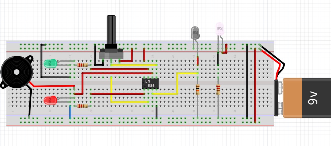
This is the Op amp that will perform an important role in this build, The job of the IC is to serve as a comparator to compare various voltage levels that appear at the inverting and non-inverting terminals. The IC can be powered by pin 4 and pin 8 following the notch alignment on the body of the Op-Amp you’ll know where to begin your counting and the diagrams below will serve as a guide
While using the Op-Amp, we are going to leverage the full functionality of it by using the 2 internal comparators to enable the sensor to detect obstacle at a specified range and also when there is no obstacle within
I conducted a little experiment on the LM358 to see its mode of operation...
With this, we can see that to get a HIGH OUTPUT; the Non inverting voltage has to be higher than the inverting voltage.
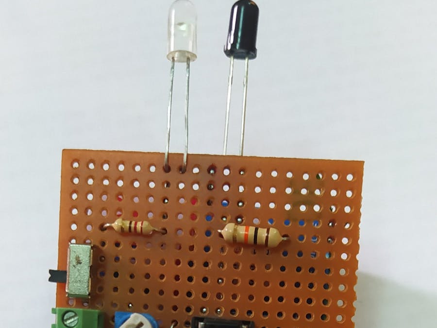
2.INFRARED EMITTER: It's emits Infrared light which cannot be seen by the visible eyes, which is reflected on the object and bounces back to the receiver.
3.INFRARED RECEIVER/PHOTODIODE: it receives the infrared rays by the emitter and thus allows more current to flow through it which generates more Voltage. it’s the main sensing device in the circuit. It doesn't emit any infrared light rather it absorbs
4.POTENTIOMETER10k: It's used to set a fix reference voltage in order to compare it with the voltage level from the IR receiver
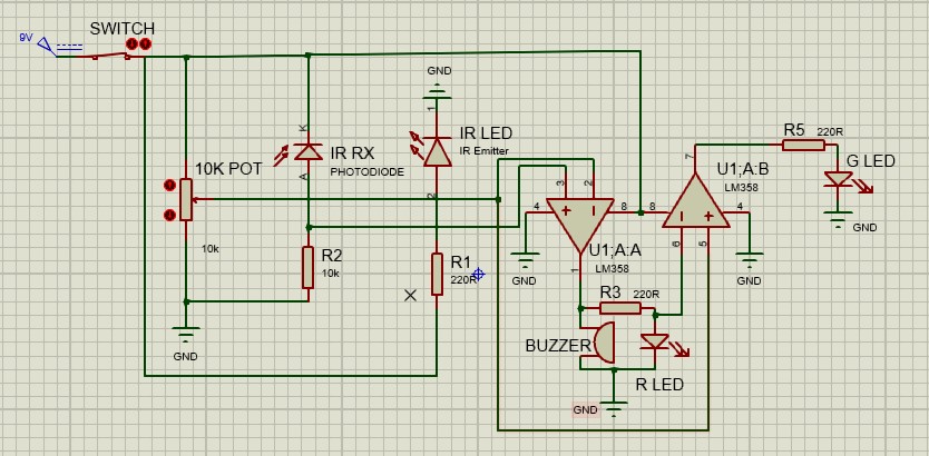
CIRCUIT DIAGRAM1. The INFRARED EMITTER is connected to be constantly turned ON to release the INFRARED LIGHT that will strike the object and in turn fall on the Infrared RECEIVER. The positive terminal of the infrared Emitter is connected to a 220 ohms resistor and the negative terminal to ground
2. The INFRARED RECEIVER is connected such that the Negative Terminal is connected 9v and the positive Terminal to the 10kohm Resistor then to ground, to enable it to read the voltage drop across the resistor which will be used in the comparator (LM358)
3. The POTENTIOMETER is also connected and the Middle pin serves as the voltage divider pin which the reference voltage is set by tuning the knob and measuring it with the multi-meter. (The 1ST and 3rd pin are connected to 9v and Ground or Vice versa)
4. The LM358 is connected and by following the “Pinout” the Op-Amp is supplied power and ground, For the 1st comparator in its job is to indicate when there’s an obstacle in front of the sensor by displaying a Red LED and activating the Buzzer to beep.
The 2nd comparator does the opposite, its job is to indicate when there’s no obstacle in front of the sensor by displaying a green LED. Voltage across the 220 ohm resistor (RED LED) is connected to the INVERTING pin of the LM358 and the fixed potentiometer voltage is connected to the NON-INVERTING pin of the LM358
Thereby the voltage values can be compared, when the Voltage from the 10k ohm resistor(Infrared Receiver) is greater than the fixed reference voltage (10k potentiometer) the OUTPUT 1 of the LM358 goes HIGH(ON) and both the LED and Buzzer goes HIGH and whenever the voltage values at the potentiometer is more than that of the 220-ohm resistor, the OUTPUT2 go HIGH (ON).
BUILD


Comments
Please log in or sign up to comment.