

Hardware components | ||||||
 |
| × | 1 | |||
| × | 1 | ||||
 |
| × | 4 | |||
 |
| × | 1 | |||
Software apps and online services | ||||||
| ||||||
Hand tools and fabrication machines | ||||||
 |
| |||||
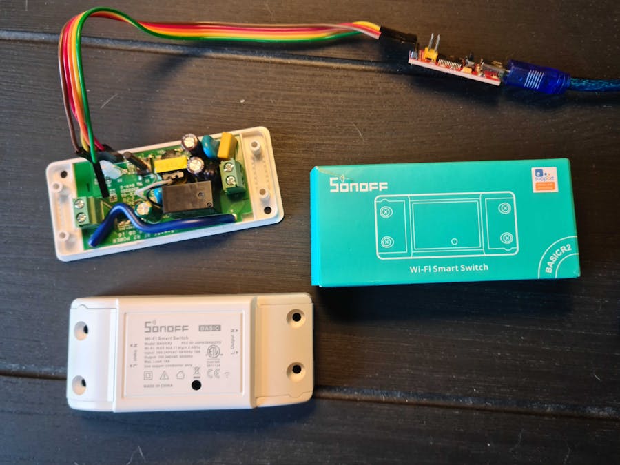
In this project, I connected a Sonoff Basic to the Arduino IoT Cloud. Sonoff devices are popular, reliable and widely available devices that allow smart control of your appliances via your phone!
The Arduino IoT Cloud is a platform that allows you to program and create custom dashboards for controlling your devices.
The cloud service supports the provisioning of ESP32 & ESP8266 microcontrollers. The Sonoff Basic is based on a ESP8582 chip (supported by the cloud), and so I wanted to see if I could program and control it using the Arduino's own cloud service: and it worked just great!
Let's take a look at how to set it up!
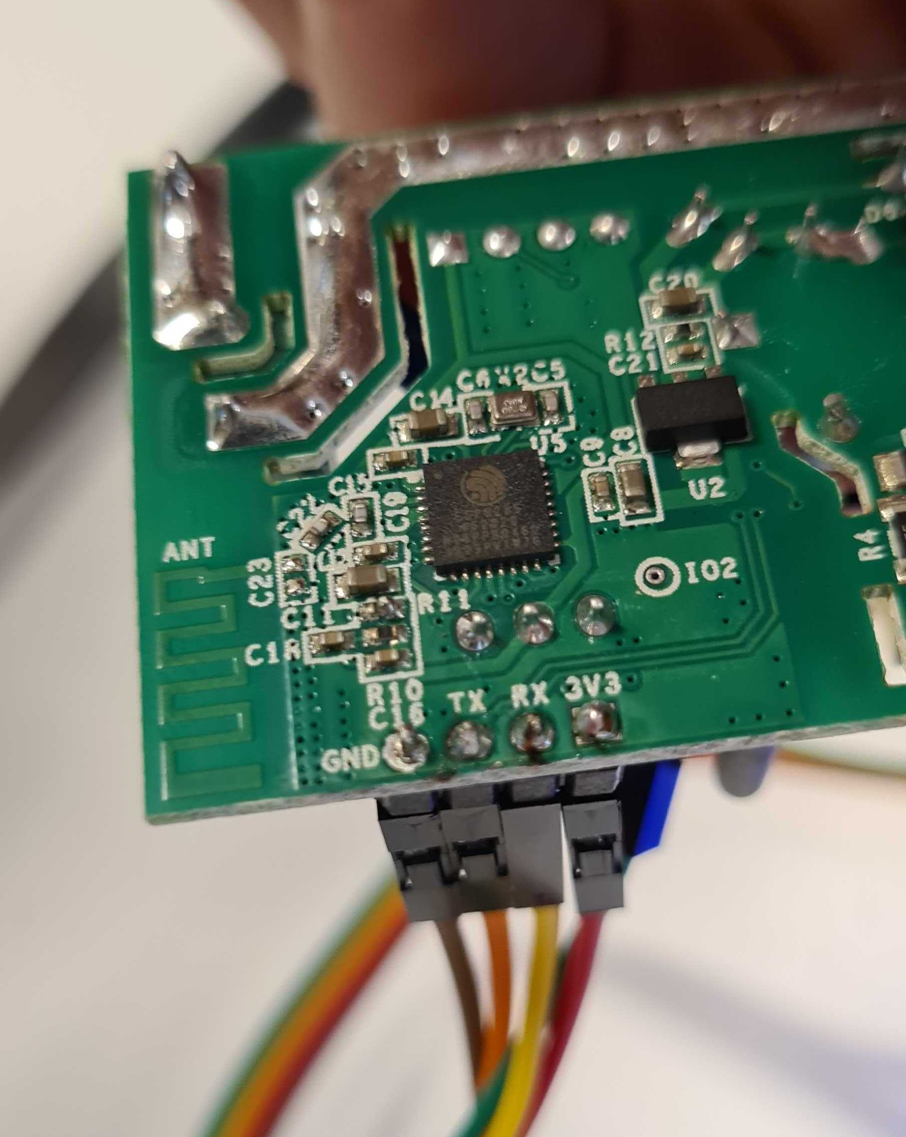
Configuring Sonoff Basic (ESP8285)The Sonoff Basic is based on the ESP8285 controller. It has 4 easily accessible pins that we need to program it (3.3V, GND, RX, TX). Simply solder a row of male header pins so that you can easily connect a USB to Serial converter.
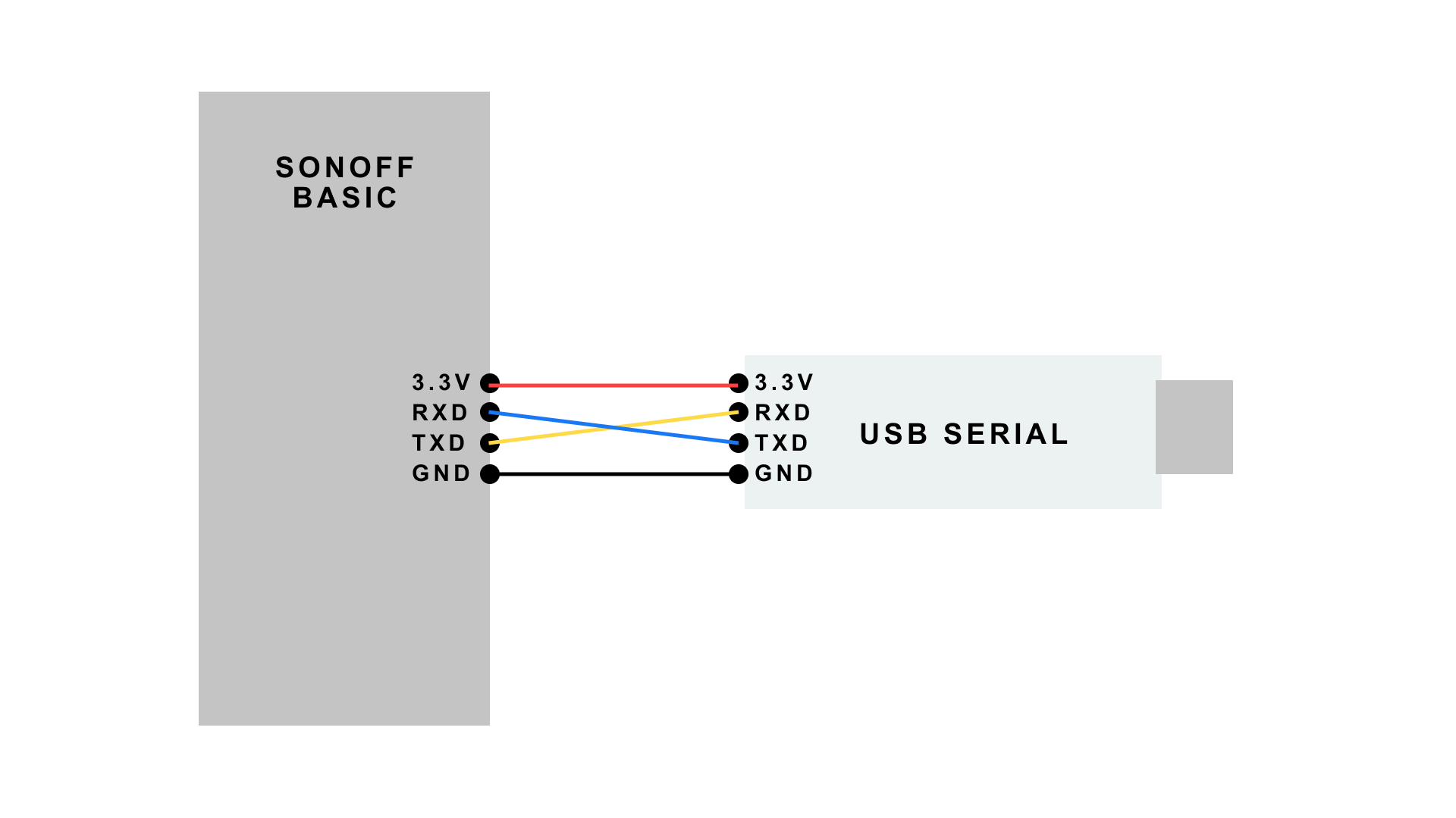
To access the circuit, you will need to open up the Sonoff casing, then you will need to connect a USB to Serial converter according to the description below:
- 3.3V - 3.3V
- GND - GND
- RX - TX
- TX - RX
Warning! Please make sure that your USB > Serial Converter has a 3.3V output. DO NOT connect the 5V to the ESP8285, as it is designed for 3.3V and will be damaged.
And that is it! Let's configure the Arduino Cloud next.
IoT Cloud1. Create Thing
To connect the IoT cloud to a Sonoff device, first go to https://create.arduino.cc/iot/things (you need to create an account). Then, click on the CREATE THING button. Create a variable called relay, which is a boolean. Make sure it has read & write permissions.
Then, click on SELECT DEVICE and choose 3RD PARTY DEVICE (then choose "generic ESP8285 module" as board later on). In the end, you will receive:
- device ID
- secret key
Make sure to save them in a good location.Now you can add your network credentials in the NETWORK section. This is your WiFi's NAME and PASSWORD, as well as your device's SECRET KEY, which you retrieved in the device setup.Your thing should look something like this now:
2. Edit Sketch
After your thing is created, click on the SKETCH tab. Copy paste the code from the snippet below:
#include "thingProperties.h"
//define the outputs
int relayPin = 12;
int ledPin = 13;
void setup() {
  // Initialize serial and wait for port to open:
  Serial.begin(9600);
  pinMode(relayPin, OUTPUT); //define relay as output
  // This delay gives the chance to wait for a Serial Monitor without blocking if none is found
  delay(1500);
  // Defined in thingProperties.h
  initProperties();
  // Connect to Arduino IoT Cloud
  ArduinoCloud.begin(ArduinoIoTPreferredConnection);
  /*
     The following function allows you to obtain more information
     related to the state of network and IoT Cloud connection and errors
     the higher number the more granular information you’ll get.
     The default is 0 (only errors).
     Maximum is 4
  */
  setDebugMessageLevel(2);
  ArduinoCloud.printDebugInfo();
}
void loop() {
  ArduinoCloud.update();
  //leave the loop empty
}
void onRelayChange()  {
  // Add your code here to act upon Relay change
  if (relay) {
    digitalWrite(relayPin, HIGH);
    digitalWrite(ledPin, HIGH);
  }
  else {
    digitalWrite(relayPin, LOW);
    digitalWrite(ledPin, LOW);
  }
}
This is a simple sketch that will only control the relay (connected to GPIO12). It works as follows:
- When
relayistrue, turn ONrelayPinandledPin(write a HIGH state). - When
relayis false, turn OFFrelayPinandledPin(write a LOW state).
And that is all!
3. Create DashboardAfter you finish the thing setup, you will need to create a dashboard to control the device.
Go to DASHBOARDS tab, then BUILD DASHBOARD. In the dashboard, click on ADD, then SWITCH. Then link the SWITCH widget to your relay variable (created in the thing setup). Your dashboard should look like this now:
Programming the ESP32 (Sonoff)
With the Sonoff circuit completed and IoT Cloud configurations done, let's try to upload the sketch to the device.To upload the Arduino sketch to this device, follow the steps below:
1. Open the sketch tab in the IoT Cloud
2. Make sure that your USB to Serial converter is connected properly (otherwise go back to the start of this tutorial).
3. Press and hold the reset button onboard the PCB (see image below), and connect the USB > Serial converter to your computer.
4. The LED on the Sonoff Basic should now be OFF. If it is red or blinking blue, try to disconnect and connect again (while holding the reset button).
5. The ESP8285 should now be in bootloader mode, and the port should be detected in the dropdown of available boards in the SKETCH tab in the IoT Cloud.
6. Click on the upload button. The uploading process will take a while, DO NOT DISCONNECT until it is finished.When it has finished uploading, it will take some time for the ESP device to connect to the WiFi network, and to the IoT cloud.
You can open the Serial Monitor for information regarding your connection.
Controlling the Device
Go back to your dashboard (with the Switch widget), and test it out. If successful, it should turn on (the relay will click, and the LED will be ON). This means you have successfully connected your Sonoff Basic to the Arduino Cloud!
You can now use your Sonoff Basic device to control real life applications, such as light sources. Always be careful when working with high voltage sources and consult an expert if you are in doubt.


_3u05Tpwasz.png?auto=compress%2Cformat&w=40&h=40&fit=fillmax&bg=fff&dpr=2)
Comments
Please log in or sign up to comment.