

About this project
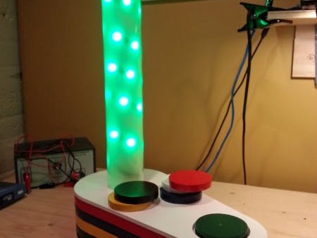
I built an interactive RGB lamp. The lamp has no switch and no dimmer, it’s entirely controlled with radio frequency identification (RFID) tags. The RFID reader is hidden in the lamp body and the RFID tags are embedded in colored wooden disks.
You can change the color of the lamp by placing a colored disc into the circular recess in front of the lamp body. When no disc is placed in the receptacle, the lamp changes color randomly. Place the white disc to produce a white light and the black disk to turn off the lamp. You can also turn the lamp into a stroboscope or produce other special effects by combining different sequences of colors. The body of the lamp and the RFID disks are made out of scrap wood I had in my shop. The shade is made from a transparent drawing tube and tracing paper.
Testing the final Arduino shield assembly
The Circuit
(this section is illustrated by the images above)
Since all this is controlled by an Arduino micro-controller, building the circuit as an Arduino shield would make it more compact and reusable. The arduino shield PCB design will be explained in the next section.
The RGB channels are driven by the Arduino pulse with modulation (PWM) output pins 3, 5 and 6. The three Arduino logic pins are connected to the gate of three N-Channel Mosfet transistors. You can control the intensity of each channel by writing values from 0 to 255 on any of these pins. The RFID reader communicates with the Arduino micro-controller through a serial connection. I wanted to be able to re-program the lamp without having to disconnect the RFID reader so I decided to use the SoftwareSerial library. This library allows you to use the IO pin of your choice for serial communication, freeing the pins 0 & 1 for communication with the computer. I used pins 8 and 9 of the micro-controller to communicate with the RFID reader. The power is provided by a 12v 600mA wall transformer. The 12v pin of the transformer is connected to the power wire of the LED strip and to the Vin pin of the Arduino. I added a small LED to indicate when the RFID reader is ready to read a new tag. This LED is connected on pin 7 of the Arduino micro-controller. Finally, an optional piezo speaker can be attached to pin #10 of the Arduino bord to integrate sounds in the project. The “ready” LED and the piezo are optionals.
A few pictures of woodworking
Woodworking
I love woodworking and I love electronics so mixing both into a single project was pure fun. I used Stketchup to do draw the lamp and test the design. The plans are available on my Github account at https://github.com/pchretien/rgbrfid.
(as seen above)
To build the body of the lamp I cut two pieces of 1/4″ plywood and four pieces of 3/4″ pine. To cut the shape of the lamp I printed a 1:1 template of the lamp using a TOP / Wire-frame view in Sketchup and glued it on top of the boards. To make sure the boards stayed aligned during cutting, I put some carpet tape between all pieces. (this trick from the best woodworking show on Youtube woodworkingformeremortals.com).
Once the shape of the lamp is cut, remove the two plywood boards and trace a line 3/4″ inside the outline of the lamp. Again, using the band-saw, cut the inside of the lamp. It’s now time to sand all the pieces and apply several coats of spay paint.
The six wooden disks are cut from a piece of 1/4″ plywood. Each disk is made gluing two 1/4″ disks together. Do not forget to place the RFID tags between the two pieces of plywood. I used a 1 1/2″ Fostner bit to make a shallow recess to fit the RFID tags. Sand and paint the disks with the colors of your choice.
Finally, I used a PVC pipe to hold the LED strip. I painted it white, cut a hole on top of the lamp and placed the pipe into the hole with epoxy glue.
For more pictures, visit the original blog post.
Github: Arduino code, the Sketchup drawing and the Fritzing circuit schematics
See this project in...
The RGB/RFID Lamp in action
Breadboard prototype of the lamp.
RGB / RFID Lamp Circuit (Breadboard View)
The Arduino Shield (full assembly instructions on blog post)
The Arduino Shield
This project was a perfect fit for a custom Arduino shield. I designed the shield using Fritzing, an open source application that allows you to build your circuit and PCB at the same time. The circuit has been designed as a single side PCB shield.
You can find the Fritzing project on my Github repo at: https://github.com/pchretien/rgbrfid
Full assembly instructions can be found here.
RGB / RFID Lamp Sketchup Drawing
Assembly
Assembly
(illustrated in images above, more pictures can be found on the original blog post.)
I assembled the lamp with my youngest kid… Here is an overview of the process.
- Wrap the LED strip around the PVC pipe and mark where it should be glued to cover the whole length of the pipe
- Glue the LED strip onto the pipe and pass the wires through a hole at the bottom of the pipe
- Attach the RFID reader under the disk holder with small wood screws
- Attach the Arduino to the bottom of the lamp
- Glue the small LED in the center of the disk receptacle through a small hole
- Strip the transformer connector, pass it through a hole on the back of the lamp and make a knot
- Connect all the wires and connectors to the Arduino shield
- Screw the bottom of the lamp and install the rubber pads
- Et voilà!


Comments