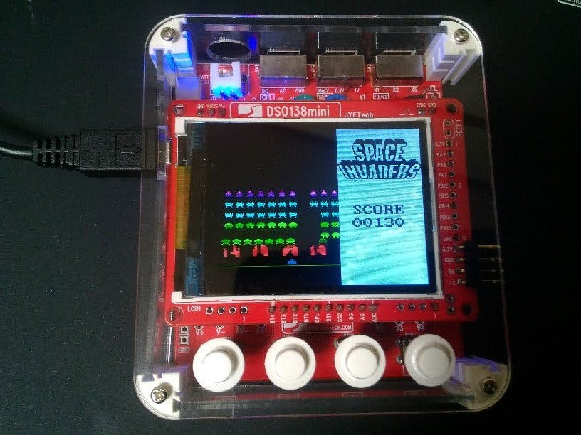
DSO138mini is Oscilloscope DIY Kit by JYETech.( Please Show https://jyetech.com/dso138mini-oscilloscope-diy-kit/ )
This Kit is a nice toy on STM32F103C8T6, TFT LCD(320x240) and 4 x button. So you would install Arduino_STM32 to this board.
And surprisingly, you could also create a game console!
Install STM32duino-bootloaderSTM32F103 will be in DFU mode if "BOOT0"pin is HIGH and "BOOT1" is LOW when booting.
Therefore, you should make JP1 and JP2 are wired by solder, at first.
Next, prepare bootloader.
"STM32duino-bootloader" is so useful, It keeps DFU mode for a few seconds when booting. By that makes it is able to write Arduino scketch with only USB cable. Please Show https://github.com/rogerclarkmelbourne/STM32duino-bootloader
However, this program needs to be customized. According to the schematic of this board ( https://jyetech.com/wp-content/uploads/2019/01/dso138-mini-schematic-main-i.pdf ), PA12(USBDP) pulled up by PA7.
Therefore we should output HIGH to PA7 port when booting. So I have prepared forked repository. https://github.com/phillowcompiler/STM32duino-bootloader_DSO138mini
There is ./binaries/dso138mini_boot20.bin
You will be able to write customized bootlader with the following tools.
- STM32 Flash loader demonstrator (needed USB-Serial, e.g. FT232RL)
- STM32 ST-LINK utility (needed ST-Link, PA13 is SWDIO, PA14 is SWCLK)
- Arduino_STM32 Tools
After flashing the bootloader, remove solders at JP1 and JP2.
platformio.iniWe will develop DSO138mini by PlatformIO with flashing by USB cable. The settings are as follows.
[env:genericSTM32F103C8]
platform = ststm32
board = genericSTM32F103C8
framework = arduino
board_build.core = maple
upload_protocol = dfuThe LCD on this board is "S95417" on "TFT7787" as LCD-Controler. It can be controled by 8bit parallel and like ILI9341( LCD you really love;-) command.
DataSheet:
https://www.displayfuture.com/Display/datasheet/controller/ST7787.pdf
So the LCD initial command will probably be...
writecommand(0x11);    // SoftReset
writecommand(0x36);    // Setting LCD Direction
// for DSO138mini(MY,MX,MV,ML,RGB,MH,0,0)
writedata((1<<7)|(0<<6)|(1<<5)|(0<<4)|(0<<3)|(0<<2));
writecommand(0x3A);    // Setting color
writedata(0x05);       // RGB565
writecommand(0x29);    // LCD ON
when drawing LCD, you should be able to use 0x2A-0x2C command.
writecommand(0x2A);
writedata(xs);        // X start
writedata(xe);        // X end
writecommand(0x2B);
writedata(ys);        // Y start
writedata(ye);        // Y end
writecommand(0x2C);
writedata16(color);   // push colors(RGB565)
writedata16(color);
....This board has 4-buttons connected PB4-PB7. Sensing "LOW" when one is pressed.
If you can do so far, you will be able to make games!
Plz Show, https://github.com/phillowcompiler/DSO138mini_Sketches/tree/master/DSO138mini_SpaceInvaders


_3u05Tpwasz.png?auto=compress%2Cformat&w=40&h=40&fit=fillmax&bg=fff&dpr=2)
Comments
Please log in or sign up to comment.