The ‘Hot Spotter’ is an autonomous drone capable of discovering smoldering fires and reporting their location. The drone achieves this by creating a heat map which it generates in realtime by combining the data from a thermal sensor (MLX90614ESF-BCC), distance sensor (LIDAR-Lite V3), position sensor (GPS), and the orientation of the drone (attitude telemetry via MAVLink).
The primary build of the drone follows the kit (KIT-HGDRONEK66) instructions which can be found here: https://nxp.gitbook.io/hovergames/userguide/getting-started
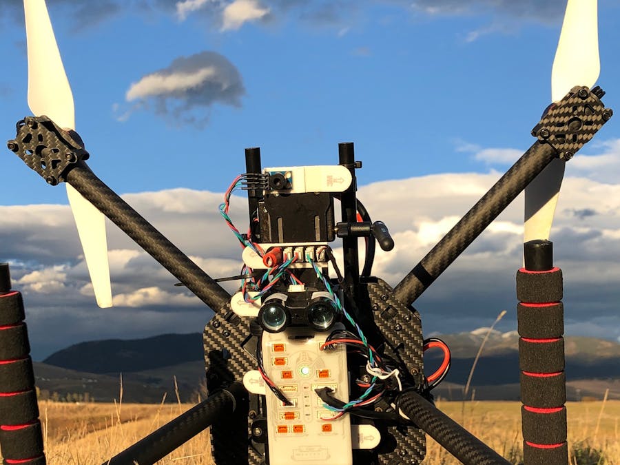
For this application the distance and thermal sensor are mounted to face the ground while the drone is in flight. I choose to repurpose the battery mount as a sensor mount:
The LIDAR-Lite V3 sensor is wired in the i2c configuration as per the instructions on docs.px4.io and connected to an i2c hub along with the thermal sensor. The i2c hub is visible in the middle of the above image above. A 680 microfarad electrolytic capacitor is attached to the i2c hub (left) to handle spikes in current from the the LIDAR-Lite and 5v is supplied to the hub as well (right). I choose to supply the 5v from pins on the onboard Raspberry Pi.
I repositioned the flight controller and other components a few times which will explain the next image. However the connections remain the same.
The Raspberry Pi (Model 3 A+) is powered by a 5V BEC which is connected to the battery via the power distribution board. The i2c hub is powered by the 5V provided by the GPIO on the Raspberry Pi.
Wiring:Wiring up the Raspberry Pi to the flight controller isn't too difficult although I was quite good and crossing wires and frying components so do be carful. Depending on the ARM architecture of the particular Raspberry Pi model there may be some hiccups installing the required MAVSDK and MAVSDK-Python. I wrote a separate tutorial for that process along with wiring tips here:
Code Description:The code I wrote for generating the heat map is available on GitHub here: https://github.com/physicsman/Hot-Spotter/tree/master/beta
Unfortunately, my Python was a little rusty and the implementation makes heavy use of dictionaries instead of classes.
The file ‘spotter.py’ is responsible for aggregating telemetry and making decisions. I realized early on that the heat map could be made more precise if I was able to determine the attitude and location of the onboard thermal sensor. Therefore, we use the quaternion attitude reported by the FMU and a vector that represents the orientation of the thermal sensor relative to the vehicle to determine the pointing of the thermal sensor for a given measurement.
The file ‘heatmap.py’ is, unsurprisingly, responsible for generating the heat map. During operation a heat map is generated on an imaginary grid overlaid onto the ground and only points that have been observed by the thermal sensor are recorded. It is important to note that the heat map does not record temperatures for points on the ground. Rather, it estimates the thermal variation among these points. Thresholds for that variation can be used to discriminate between warm areas and fires.
Since update rates for GPS and other control variables can vary on timescales of 5hz or slower the estimation used during sensor fusion needs to be filtered to improve the accuracy of the estimated thermal sensor pointing and thus the overall fidelity of the generated map. At the moment this is achieved by simply recording the timestamp and value for the two most recent readings of each sensor. Each time we record a value from the thermal sensor we linearly extrapolate the value of each sensor to the current time. A more sophisticate filtering could be implemented in the future to further increase the fidelity of the heat map.
To determine which points on the ground are in the field of view of the thermal sensor at any given time we select points on the ground beneath the vehicle in a reasonably sized radius and determine, from the current pointing estimate of the thermal sensor, which of those points lay in the field of view of the sensor. By taking measurements of the same point from multiple vehicle positions we can build a heat map which shows thermal variation and accounts for the likelihood that a given point on the ground contributes to that thermal variation.
Postface:- Distance sensor: Strictly speaking the LIDAR is not needed if the drone is to be flown at a known safe altitude. The sensitivity of the heat map will be slightly reduced as distance above ground is estimated instead of directly measured. However the addition of LIDAR opens up the possibility of terrain following, obstacle avoidance and generally increases the utility of the drone.
- Thermal sensor: I've found that is much easier to off-board the thermal sensor to the companion computer (RPi). It is quite simple to enable I2C on the RPi and there are numerous Python implementations already on GitHub for reading the MLX90614 on the RPi (https://github.com/CRImier/python-MLX90614).
- Thermal sensor pointing: Precise alignment of the thermal sensor with respect to the vehicle is difficult. However, I suspect the error could be automatically calibrated for by minimizing the variance of a heat map with respect to small variations in the assumed pointing vector of the thermal sensor. This could even be done in situ during each flight.


Comments
Please log in or sign up to comment.