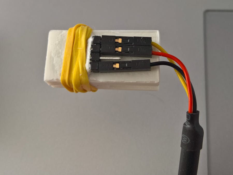
This is an example of a simple quick-connect serial clip that can connect a PCB- mounted ESP8266 to a computer via USB.
If you don't want the expense or bother of soldering on a fancy USB connector to your many IoT PCBs for flashing and/or programming your ESP (or other) device, you have options. I worked out an easy, cheap, and reliable method of making a quick short-term connection. You need a few things. Some parts you need to buy; some you need to 3D print. If you don't have a 3D printer, you need one now.
The parts I've detailed in the "Things" section are for my particular project; however, it would be easy for anyone to adapt my plans to a particular project. The 3D-printed clip (download below) is designed to hold the four-position spring connector against a four-position 2.54mm header on the target PCB with the offsets detailed in the diagram below.
If you need to change the offsets on your target PCB then you'll need to update the 3D-printed clip. You'll need to use something like 3D Builder or ACAD.
You'll need to solder the four-position spring connector and the four-position right angle through hole connector to the optional small SMT PCB. If you don't use this PCB, you'll need to solder the right angle through hole connector to the four SMT pads of the spring connector, but that's hard to do and not very reliable. It's easier to just use the optional Upverter SMT PCB that you can download below. It's small and would be easy to include on your next PCB design as a panelized part.
After printing the clip design, you'll have two parts as shown in the diagram below. The part on the left has the hole for the connectors. The part on the right positions the connector on the target PCB. We'll connect them together later.
After assembling the spring connector, the small SMT PCB, and the right angled connector with the connector side of the 3D-printed clip you'll need to secure it into the left part with ABS juice or something similar to fill in the space on the through hold connector side. If you're not familiar with ABS juice you need to stop what you're doing and research this now! Just be careful with the acetone. It's something every ABS 3D printer artist needs to know intimately. After the juice dries, the left part should look something like this.
Now you're ready to assemble the two parts of the clip together and connect the USB cable to the header connector. I used a small rubber band. You can adjust tension of the clip by varying how tightly you wrap the rubber band. You'll need to ensure correct connections to the TX, RX, and GND, and that depends upon the schematic of your target PCB.
After that you're ready to connect to your target PCB and communicate. Make sure you use the notch in the non-connector side of the clip to fit onto the target PCB.
I've found this type of connection useful and reliable for quick short-term communication sessions.


_t9PF3orMPd.png?auto=compress%2Cformat&w=40&h=40&fit=fillmax&bg=fff&dpr=2)


Comments
Please log in or sign up to comment.