My wife’s interest in stained glass and glass fusing is the inspiration for this project. She has a small glass kiln that has an electro-mechanical controller for adjusting the kiln temperature. Since glass fusing is a multi-step process that needs precise heat control, it was next to impossible to control the kiln temperature with such rudimentary adjustments. I was determined to take the guesswork out of controlling the heat manually, to one where the various heat cycles were under software management. The hardware design in this project was the first step in attaining that goal.
I decided that the RPi Zero W would be the perfect mate for this job. It is small, cheap, and has built-in WiFi. I picked one up on sale at a local retailer for $5.00, but I think they normally sell for a little more. My long range aspirations for this project was to have a programmable kiln controller that could be initiated and monitored by a cellphone, tablet, laptop, or PC, but first - part 1 - the hardware!
I want to say up front that I am definitely no expert in hardware or software. I pretty much teach myself what I need to know when I need to know it, and then I usually end up forgetting how I did things in the first place. So please be kind with your criticisms and take from this project anything that may be of help to you as I have taken much from others.
So if you already have Raspbian installed in your Pi and you have a monitor hooked up to it, that’s great. You also will need a Python script editor (like Geany) so that you can copy and paste the code easily and play around with modifications.
If you are just getting started here is a link to a tutorial from SparkFun that will teach you all you need to know about how to get Raspbian installed and your Pi connected to the internet.
https://learn.sparkfun.com/tutorials/getting-started-with-the-raspberry-pi-zero-wireless/all
It is not necessary to have a monitor, keyboard, and mouse connected to your pi in order to complete this project. Mine is running without those (headless). Here is a link to tutorial that helped me accomplish this.
https://liftcodeplay.com/2017/07/03/how-to-run-a-headless-raspberry-pi-with-vnc-viewer/
My thanks to the people at the links above for providing me with the information I needed to get my project up and running.
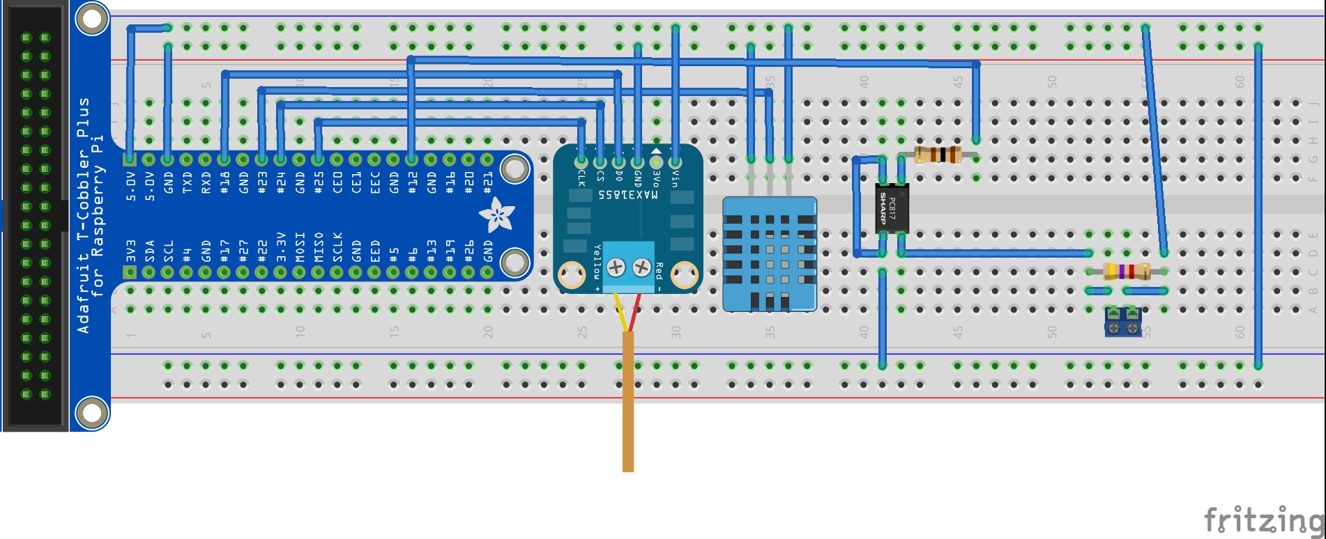
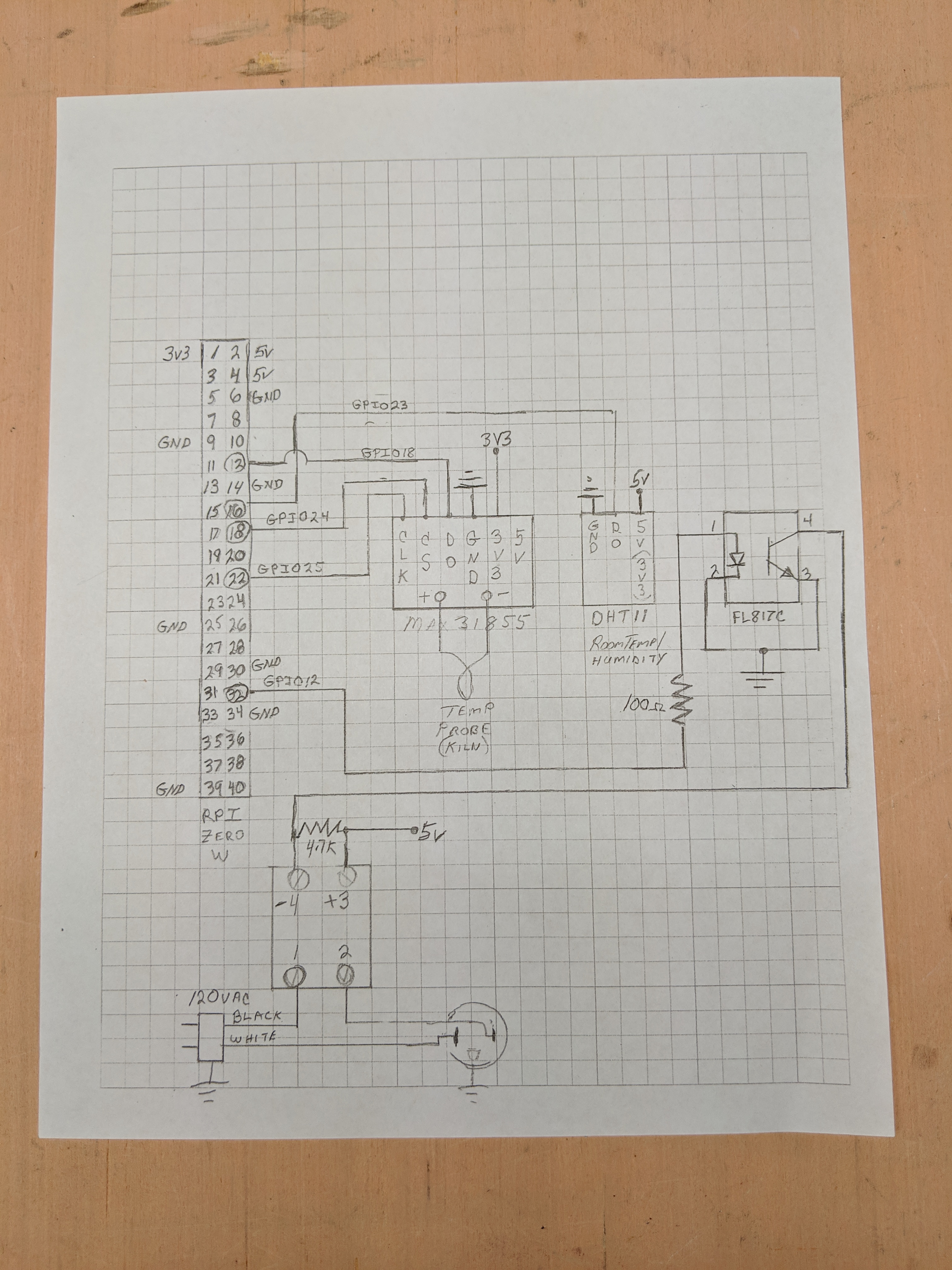
Now you are ready to assemble the hardware.
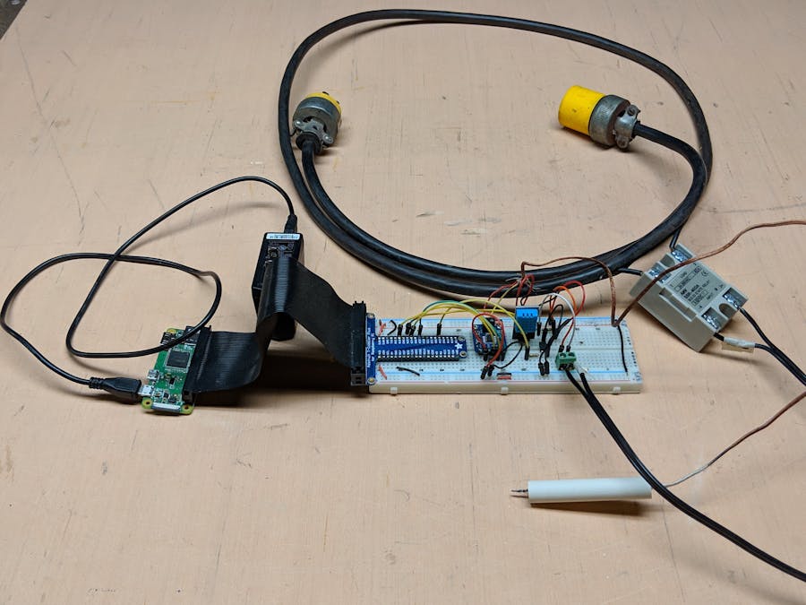
I built this project first using a solderless breadboard.
I next went on to make a more stable version of it on a piece of perf board. If you are going to do this, you will need a second rpi zero w. I found it much easier to mount the 40 pin header with the pins facing the bottom of the board.
This made it easier for me to make connections to the pins on the pi.
Seems like a lot of projects end up staying on a breadboard, but if you're serious about actually using this for something useful, I recommend a more permanent solution. My cat was quite intrigued by the whole thing. Something about wires that cats (at least mine) can't seem to resist. My cat once chewed through a string of Christmas lights!
To power the device, I went rummaging through my 40 year old collection of various power supplies and wall warts (yes I've been collecting them for at least that long.) The one listed on this post looks similar to the one I am using. Mine says AC/DC adapter 5vdc 1 amp. I have had no problems with it.
The solid state relay I chose is rated at 40 amps. The input voltage says 3-32vdc. Once again, I had no issues with it either. Although you can take that endorsement with a grain a salt, because the only thing I have it operating is the heating coil of a kiln.
I found an old short extension cord in my shop and used it to connect the relay to. I slit the insulation and then cut the black wire. I connected one end of the black wire to Load 1 and the other end to Load 2. Now I can't actually tell you whether it makes a difference whether you connect the plug end to Load 1 or to Load 2, but mine is connected to Load 1.
According to some information I found at this website https://www.thermocoupleinfo.com/thermocouple-wire.htm "a type K thermocouple is made when a wire of Nickel-Chromium is welded to a wire of Nickel-Alumel. The grade of the wire is dependent not only on the combination of alloys used, but also on the purity of those alloys."
I found this wire in one of those spots where I keep things that I'm not quite sure what they're for but I'm pretty sure I made need it some day :). Mine wasn't welded together but I had nothing to loose by twisting it instead. It worked! Go figure. Now if it hadn't worked I would have had to buy one, so I put a link in the materials section that may help you find something.
From what I have read, typically the red wire is negative and the yellow positive, so keep this in mine when connecting the type K wire. Since I needed to put the probe inside of the kiln, I wanted an insulator to put around the wire that could withstand the heat of the kiln (temperatures up to 1500 degrees Fahrenheit.) I went looking through a junk drawer and found a ceramic tube to put around the wire for an insulator.
After the hardware is complete, you can begin playing around with the many ways you can use this project board as a programmable AC extension cord. I say "programmable" because you don't have to use the temperature sensors on board if you don't want to. You can change the code to anything you like. Maybe you want to plug your coffee pot into it and turn it on at a certain hour. The simple python 2 script I included does not do much of anything other than provide an example of the basic steps necessary to control each of the components on the board, but I hope you see the potential to do much more with this device.
I hope to make a part 2 to this project and show how I am using it to control my wife's glass fusing kiln. That part 2 would be focused mainly on the software and how I used Node-RED, MQTT, and the Pi Zero W to allow my wife to control and monitor her kiln from any where in the house. Glass fusing projects can run for several hours to all day, so this means she doesn't always have to be at the kiln to know what is going on. It can even tweet or text her updates. But for now, all I have to offer are these general instructions for getting the board operational.
To get the code into the pi and running is not difficult at all. Open up Raspbian and go to Applications – Software – Geany.
If Geany is not already installed, open up a terminal window and type each of these commands.
sudo apt-get update
sudo apt-get install geany
Once installed, go to Applications – Software –Geany.
Once open, select File –New (with template) – main.py.
Next delete everything except the top line.
Then copy and paste the code into Geany and it should look similar to this.
You can’t get Python to actually execute your script unless it is saved with the “.py” extension. That’s why it is just simpler to open up the main.py template and use that.
To execute the script, hit F5 or select the icon of the paper airplane.
Good luck and enjoy. Any comments are welcome.


Comments
Please log in or sign up to comment.