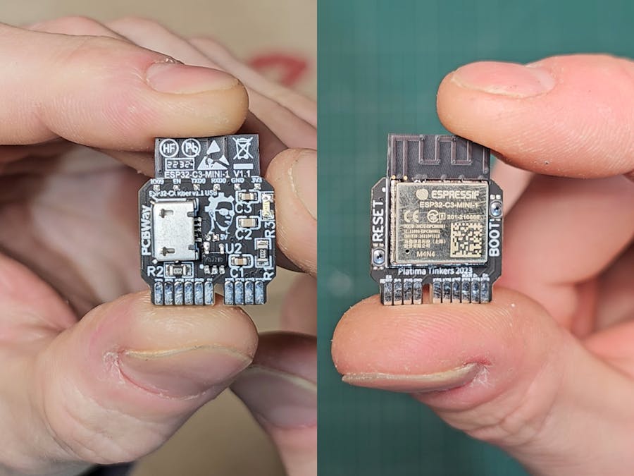
I have a LOT of ESP32 chips, and I use them in many projects, but unfortunately the modules are never quite what I want, eg: too big and bulky, no USB port, wrong mounting options, etc.
With this, I decided to design my own. I want it to be stamp sized, to support more than one module (any ESP32-C series should work ideally), have optional USB, support easy JTAG connections, and be available for all to DIY themselves.
The two key things in this design for me are mounting options, primarily because I want to keep it compact and mount it vertical for many of my projects, but then also have it highly versatile, so you can use it with 3.3V or 5V input, you don't need to have the micro USB header or buttons on there if you don't need them, JTAG access is easy etc.
The first iteration as shown in the project image was a prototype, and unfortunately did not work - I believe either my bad soldering as I used an air gun for the SMD soldering (should have been fine), or due to IO2 not being connected to anything and stuffing up the boot process. I have not yet tested them all though!
Whether or not some of them work, I decided it's a better idea to redesign it, so for v1.1 which is WIP I am adding the following features;
- Optional 3V3 LED on one pull-down pin as 'power' LED <- Done in v1.1
- Optional reset & boot (flash) buttons via exposed pads <- Done in v1.1
- Optional 3V3 regulator in case of 5V pin or USB input <- Done in v1.1
- Thinner board, ideally 1mm, as I found 1.6mm too bulky <- Done in v1.1
- Gold fingers for production version, and fixing finger width <- Partial
- Larger text for pins and pads as the previous was unreadable <- Partial
- 2.54mm spacing on the pins for compatibility <- Done in v1.1
- Header holes on the pins for optional horizontal mount <- Decided not to
- Through-holes to plug a CP2102/2104 straight onto the PCB <- Decided not to
- Move the pin keying in a bit further to improve strength <- Done in v1.1
I think I am just about done with the schematic and PCB design, with just the through-holes for the headers left before I order the next prototype. I welcome any and all input on this project and will likely upload a video to my Youtube page (https://youtube.com/@PlatimaTinkers) about the failed v1 prototype.
Thanks for reading! <3
PS: These are all available in my online shop now too; https://shop.plati.ma.
Quick GitHub Repo Link: https://github.com/platima/ESP32-CX-Riser.
UPDATE 2023-09-25V1.1 worked, and a huge thanks to PCBWay for covering the costs. Video:
UPDATE 2023-08-08V1.0 worked after lots of troubleshooting. Video:
V1.1 has been ordered and the next video will cover those improvements/changes!


Comments
Please log in or sign up to comment.