Each year, Renault hosts a contest of hacking its Twizy platform (a design based on an electric urban vehicle). We participated in that contest (via our university, Polytech Sorbonne) and came up with the idea of hacking the platform to make a pothole detection vehicle, that can update a map with the positions of the potholes in real time. Here's the promotional video we made about it (there are subtitles in English):
So how does it work?Its array of 6 infrared sensors mounted under the vehicle pointing downwards detect changes in distance between the vehicle and the road, thus detecting potholes. The system's accelerometer can also detect the potholes and abrupt shocks the vehicle experiences due to abnormal vertical variations.
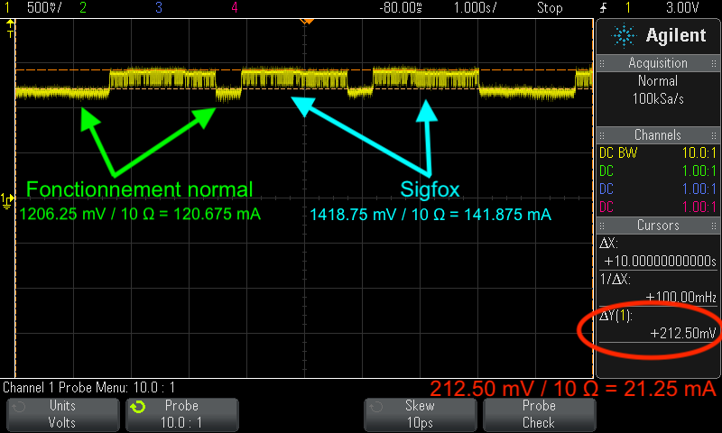
The system then sends that information (via the Sigfox module) to a backend that we made using Microsoft Azure, and then the information is displayed on a map interface we made using Power BI. The system also stores detailed data on an onboard micro-SD card in JSON format, so the user can recuperate that information in order to construct a clearer image of the severity of each pothole the system has detected.
The system is powered by a Li-Ion battery that's charged via a solar panel.
Now let's get on with how to make this project!
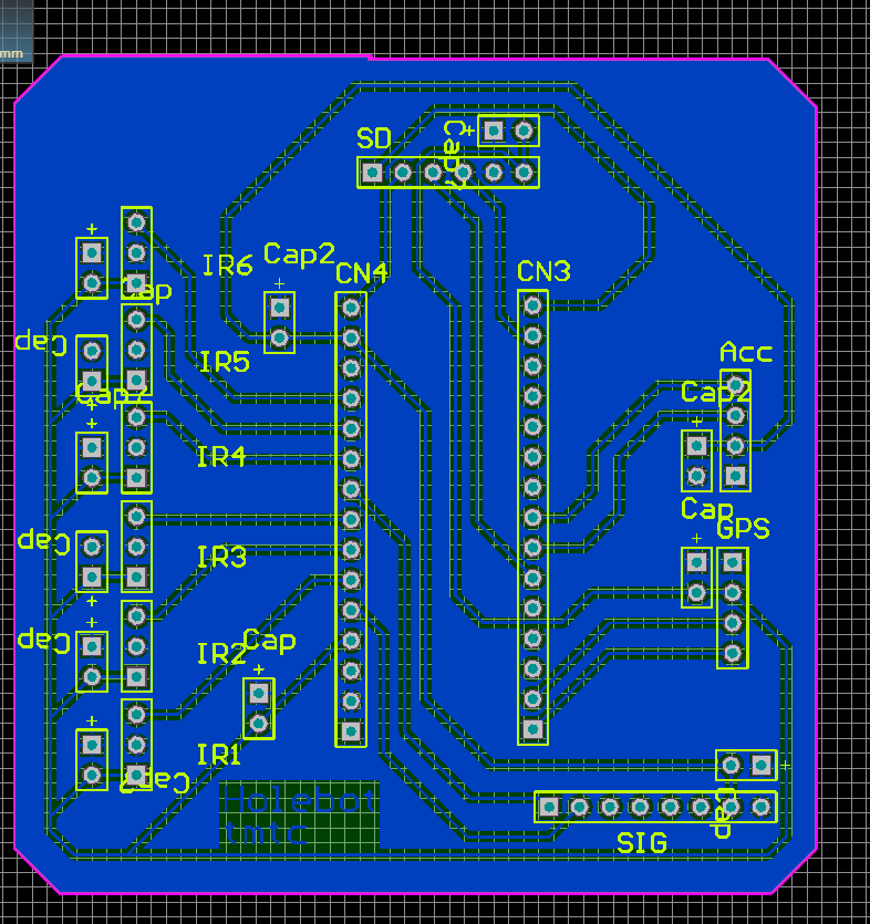
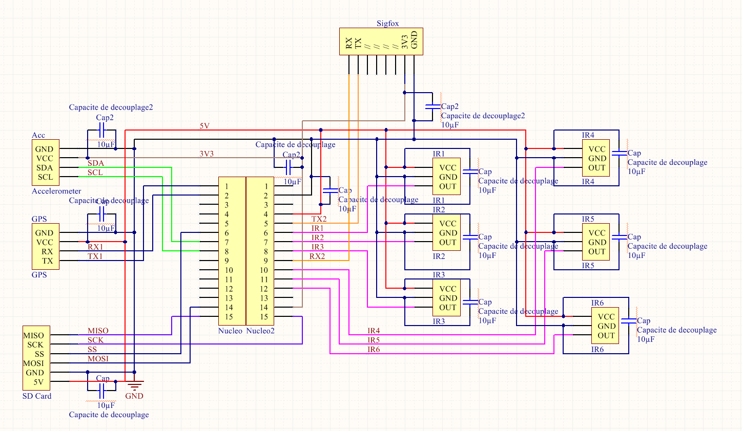
The main PCBFirst of all, you need to route a PCB following the main PCB schematic :
Once that's done, you can solder all the main components in place : The microcontroller (be careful not to put it on backwards!), the headers for the infrared sensors, GPS and accelerometer modules, the Sigfox and finally the SD module. Once all that is soldered or connected to the PCB, you can then solder on the decoupling capacitors.
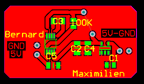
The power supply PCBNow it's time to make the power supply PCB that charges the battery and supplies a steady 5V to the microcontroller (and thus the rest of the main PCB).
You first need to route a PCB following this schematic:
The two points in the middle need to be connected, so you need to solder a jumper cable between them. Afterwards, you can solder the solar panel on the connection pads on the right of the diagram, and also solder the battery between the lower of the two middle points (the + terminal) and connect the - terminal to ground. You should now have a stable 5V between the connection points on the left. You can solder two cables to these points and connect them to the VIN and GND pins accordingly on the Nucleo microcontroller.
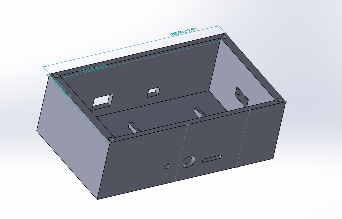
The 3D-printed casing (optional)You can make a simple box container in the modelling software of your choice, then 3D print it, so as to have a container in which you can put your electronics. This is optional (you can also buy pre-made container).
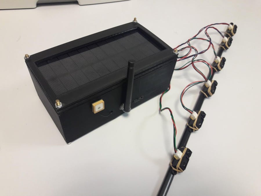
Now that everything is working on the electronics side of things, you can put everything in the container and mount the infrared sensors on a bar that you can mount to your vehicle:
On to making the backend!
The backendWe transmitted the data to the Sigfox backend. We can send it 140 messages a day. It is sufficient since we don't detect 140 pot holes a day. We send it the latitude and the longitude of the pot holes.
In order to process all the informations we collect, we chose to use Microsoft Azure since we can get a free trial for students. We configured it thanks to this github tutorial: https://github.com/aureleq/sigfox-azure-iothub
The backend is separated in two parts: Microsoft Azure to collect the informations and Power BI to process the data. In view of the messages we recieve from the Sigfox backend, we print it on a map on Power BI as you can see on the screenshot of the Story part.






Comments
Please log in or sign up to comment.