The Atmel tinyAVR MCU's are great little chips for projects but can prove difficult to debug. Some ATtiny chips do not have direct support for hardware based serial and therefore the Serial object is unavailable in your code, however, it is easy to add a SoftwareSerial object and view output in the Arduino IDE.
The code in this article uses an ATtiny85 with an FTDI Serial TTL-232 USB Cable to send or receive information. A USB Serial TTL Cable can also be used since the CTR and RTS pins are not needed.
NOTE: This cable is not used to program the AVR. To program the ATtiny85 you will need a programmer such as the SparkFun Tiny AVR Programmer.Using the Software Serial Library
The Software Serial library is straightforward to use. Start by ensuring the include statement is specified near the top of your sketch. Next, create a SoftwareSerial object specifying the RX pin (pin to receive on) and the TX pin (pin to send on) when creating the instance.
#include <SoftwareSerial.h>
// ***
// *** Define the RX and TX pins. Choose any two
// *** pins that are unused. Try to avoid D0 (pin 5)
// *** and D2 (pin 7) if you plan to use I2C.
// ***
#define RX    3   // *** D3, Pin 2
#define TX    4   // *** D4, Pin 3

// ***
// *** Define the software based serial port. Using the
// *** name Serial so that code can be used on other
// *** platforms that support hardware based serial. On
// *** chips that support the hardware serial, just
// *** comment this line.
// ***
SoftwareSerial Serial(RX, TX);
The rest of the sketch will contain standard Serial references in the same manner you are accustom to in your sketches on other Arduino boards.
void setup()
{
  // ***
  // *** Initialize the Serial port
  // ***
  Serial.begin(9600);
  Serial.println("Initializing...");
}
One important note is, that since he ATtiny has limited memory, strings inside the Serial.print() statements will consume a lot of memory very fast. This can limit either the number of Serial statements or the amount of code and/or libraries you can include. Use the strings wisely by getting creative with the way string values are used.
Connecting the USB to Serial CableRegardless of whether you are using an FTDI cable or some other USB to Serial cable, you will use at most four wire and at least three. The wires you will need are described below.
- 3V3/5V - This wire is optional and can be used to power your circuit during testing. You can power your circuit only when the current demand is limited (less than 500 mA). This wire is usually red (color may be vary).
- GND - This wire is required and should be connected to pin 4 on the ATtiny85 (or to whatever point you designated as ground). This wire is usually black (color may be vary).
- TX - This wire is used by the external device to send data to your ATtiny85. This wire should be connected to the pin you designated as RX when you setup your Software Serial instance. On FTDI cables, this wire is usually orange. On the USB to TTL Serial Cable this wire is usually green (color may be vary).
- RX - This wire is used by the external device to receive data from your ATtiny85. This wire should be connected to the pin you designated as TX when you setup your Software Serial instance. On FTDI cables, this wire is usually yellow. On the USB to TTL Serial Cable this wire is usually white (color may be vary).
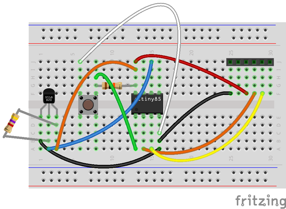
The circuit in this article demonstrates how to connect a Maxim DS18B20 temperature sensor (that utilizes the Dallas OneWire protocol) to the ATtiny85 and send the results over the serial port to the Arduino IDE.
Load the sketch onto the ATtiny85 using your AVR programmer. If you do not have a programmer, you can use an Arduino Uno (or similar board). Take a look at one or more of the articles listed below for help.
- Programming ATtiny85 with Arduino Uno on Hackster.io
- Virtual Workshop: Program an ATTiny85 with Arduino
- Programming an ATtiny w/ Arduino 1.6 (or 1.0)
- Programming an ATtiny w/ Arduino 0022
Once the ATtiny85 has been programmed with the sketch, place it onto the breadboard and build the circuit by referencing the attached schematics. The circuit is shown below.
Next, connect the Serial cable to the breadboard. I use a 6-pin header on my board to make it easy to attach and detach the cable. With the cable attached, the ATtiny is now powered up and running. The next step is to monitor the serial output.
Open the Arduino IDE, select the COM port of your cable and open the Serial Monitor. Note that the Programmer option in the IDE needs to be set to AVRISP mkil for this to work. If you are using a USBtinyISR to program your ATtiny85, just change it in the IDE when you have completed the programming step.
Since the chip is already running, you probably will not see the messages that were sent in the setup() routine. Just press the reset button on the breadboard to restart the program.
The video below is a demonstration of the output in the Serial Monitor.
I will not cover it in detail, but you can also use a program like Putty to monitor the serial port. Just start Putty, select the Serial option and type the name of the serial port (like COM3).


_1x_bGT19vVAby.png?auto=compress%2Cformat&w=40&h=40&fit=fillmax&bg=fff&dpr=2)

_3u05Tpwasz.png?auto=compress%2Cformat&w=40&h=40&fit=fillmax&bg=fff&dpr=2)
Comments