Mountain bike wheels used spokes under large amounts of tension to make the wheel stiff. Most wheels will become deformed due to loosening of spokes and actual deformation of the rim through use. This can lead to unsafe wheels or even the tire rubbing on the frame of the bike. To fix this, you must true the wheel. Truing a wheel entails tightening spokes on either side of the wheel to bring it back in line with the center of the hub. To do this, many bike shops and at-home mechanics use truing stands. These can be makeshift or bought from certain bike maintenance companies. These truing stands use adjustable dials such as micrometers that rub on the rim wherever it deviates too much from the center. Even with a truing stand, truing a wheel may take hours and many people don’t have the time to do it properly.
Our solution to this time-consuming problem was to use two potentiometers to put out a constant and accurate feed of wheel displacement data that the user can use to true the wheel more efficiently. Through the use of indicator LEDs for making major adjustments to the worst areas of the wheel, the wheel can be brought within two millimeters of true. Then, using the data posted to ThingSpeak, the user can take measurements at every spoke to bring the wheel to an almost perfect true.
The inspiration for this project came from one Skyler’s friends from the 49er MTB Club who had taken this class a couple of semesters ago. We wanted to improve upon their design by using two potentiometers instead of one. This meant that we would not need a zeroing function and could in theory correct dents in the rim as well.
Finished Setup of Dual Potentiometer Wheel Truing Stand
Our solution (Argon 1)
Argon 1 is the first of two Argons that use the data directly from the potentiometers. It is responsible for determining if the alignment of the wheel falls within an acceptable range. It does this by pulling the voltage drop that is output by the potentiometers. We know that the potentiometer moves 14 mm and the voltage that we found at the maximum displacement was roughly 3400 mV. Knowing this, we can find the variable that turns the mV to mm, roughly 244mV/mm. The next step is to subtract the value of the left potentiometer from the value of the right. The resulting number tells us how far out of alignment the wheel is and in what direction. If the value is negative, it is out of alignment to the left, and if the value is positive, it is out of alignment to the right. The last thing that Argon 1 does is publish one of three events: RedLight, BlueLight, or GreenLight. These events are created each time a new variable is pulled from the potentiometer and are tied to one of three parameters: if the wheel is out of alignment to the left or the right, or if it is centered. These events are used by Argon 3 in its code.
Particle Argon 1
Our solution (Argon 2)
Argon 2 is the second of two Argons that take data directly from the potentiometers. Argon 2’s main responsibility is to upload the data to ThingSpeak to create a graph of the alignment of the wheel. It does this by pulling the voltage output by the potentiometers, converting them into displacement, and subtracting one from the other. This function is exactly like Argon 1. However, once the data is converted into the alignment of the wheel, the Argon will publish the data directly as a displacement. Using an integration in the Particle console, this data is sent to the Wheel Displacement ThingSpeak Channel. The data is then graphed using their software.
Particle Argon 2
Our solution (Argon 3)
The third Argon in the chain, Problem_Child, provides the system output for the truing stand through the use of indicator LEDs. When a leftward deviation greater than one millimeter is detected, the blue LED is illuminated, and when there is a rightward deviation of the same magnitude, the red LED is illuminated. When the deviation is within tolerance, the green LED is illuminated. This was accomplished by subscribing the Particle device to three separate events—RedLight, BlueLight, and GreenLight—sending a signal to turn off any other LEDs while lighting the corresponding LED. This eliminated the problem of intermittent blinking, which proved distracting and uncomfortable for the user, allowing each LED to remain lit for the duration that its condition was met.
Particle Argon 3
A previous iteration of the system output had Problem_Child display the numerical system output on a 4-digit 7-segment display, but output could not be achieved. Likewise, attempts to display the output on an LCD screen were fruitless. A further attempt to display a numerical output using a Particle Photon failed after Skyler bricked it. The group elected not to attempt to use a second Photon that was available in light of this failure.
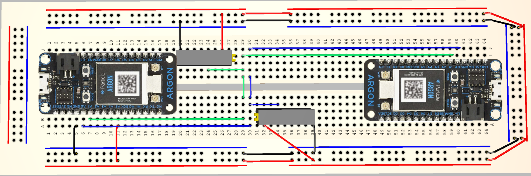
This is the breadboard schematic for the Particle Argon that posts the displacement data to thing speak and the Particle Argon that Publishes the data for the Led Particle.
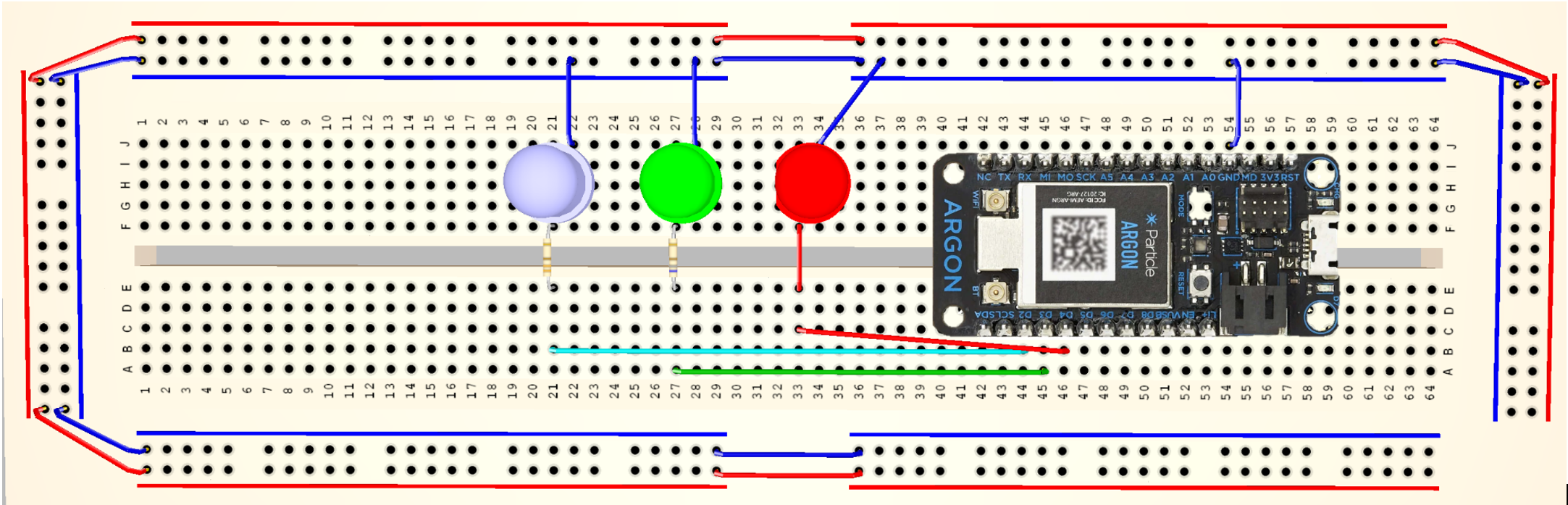
Led Indicator Particle
This Particle subscribes to the potentiometer data and shines a red, green, or blue led according to the displacement of the wheel.
This code powers both potentiometers and reads the data output from each particle. It then publishes the color led that shoud be shining based on the displacement of the wheel.
intpower=A5;doubleReading1=A0;//reading from potemtiometer 1doubleReading2=A1;//reading from potemtiometer 2doubleDisplacementdata;voidsetup(){pinMode(Reading1,INPUT);pinMode(Reading2,INPUT);pinMode(power,OUTPUT);digitalWrite(power,HIGH);}voidloop(){if(digitalRead(power)==HIGH){//determines if circuit is onDisplacementdata=0.5;if((analogRead(Reading1)-analogRead(Reading2))/244.286>=Displacementdata){//Is true if wheeel is aligned rightParticle.publish("RedLight","Red");//sends event "RED"}elseif((analogRead(Reading1)-analogRead(Reading2))/244.286<=-Displacementdata){//Is true if wheeel is aligned leftParticle.publish("BlueLight","Blue");//Sends event BLUE}else{Particle.publish("GreenLight","Green");}//Is true if wheeel is centered, Sends event Greendelay(1000);}}
Thing Speak Particle Code
C/C++
This code takes the data output from the potentiometers and posts it to Thingspeak.
intpower=A5;doubleReading1=A0;doubleReading2=A1;intDisplacementdata;voidsetup(){pinMode(Reading1,INPUT);pinMode(Reading2,INPUT);pinMode(power,OUTPUT);digitalWrite(power,HIGH);}voidloop(){StringDisplacement2=String(((analogRead(Reading1)-analogRead(Reading2))/244.286));//Turns the Voltage drop recived into the change in distnance of the potenteometersParticle.publish("Disp2",Displacement2);//Publishes the data for thinkspeak to accessdelay(1000);}
Led Particle Code
C/C++
This code subscribes to the potentiometer particles data and tells the particle which led to turn on.
//Identifies the pins powering each LEDintred=D4;intgrn=D3;intblu=D2;voidsetup(){//Identifies each of the previous pins as outputspinMode(red,OUTPUT);pinMode(grn,OUTPUT);pinMode(blu,OUTPUT);//Subscribes to three events published by POS_Volume_2, each dictating which LED to illuminate.Particle.subscribe("RedLight",Red);Particle.subscribe("BlueLight",Blue);Particle.subscribe("GreenLight",Green);}//Initiates events dependent on event "Red"voidRed(constchar*R,constchar*r){//Turns off non-target LEDsdigitalWrite(blu,LOW);digitalWrite(grn,LOW);//Turns on target LEDdigitalWrite(red,HIGH);delay(500);}//Initiates events dependent on event "Blue"voidBlue(constchar*B,constchar*b){//Typ.digitalWrite(red,LOW);digitalWrite(grn,LOW);//Typ.digitalWrite(blu,HIGH);delay(500);}//Initiates events dependent on event "Green"voidGreen(constchar*G,constchar*g){//Typ.digitalWrite(red,LOW);digitalWrite(blu,LOW);//Typ.digitalWrite(grn,HIGH);delay(500);}


_zhWsCcSEcl.jpg?auto=compress%2Cformat&w=48&h=48&fit=fill&bg=ffffff)


Comments
Please log in or sign up to comment.