


Hardware components | ||||||
 |
| × | 1 | |||
 |
| × | 1 | |||
Software apps and online services | ||||||
 |
| |||||
Often in our projects and applications, we need a way of storing the data that comes from some certain sensors, like, lets say, position, temperature, humidity, etc.
Or just a setup data required for a program to run smoothly. It is here where EEPROM memories come in our rescue, as we know it can be erased electrically and retain data even if power is gone.
Let's talk a bit of PSoC's EEPROM Memory:
If we look at its data sheet we find:
- A memory range from 512B to 2KB
- 1 million write/read cycles. Data sheet refers more to the useful life of these memories to take into account.
- Read/Write 1 byte at a time
- Program 16 bytes at a time
We can think an EEPROM, and treat it, as an array, once this concept is understood we will se how to program it. See the following figure:
We have to think that there are memory addresses that make reference to the place where we store or save the data, which for this project will be only 8 bits long.
In every memory direction there is a data, then this way, and looking at the figure as an example, we see the following:
- Address: 000 - Data :0100
- Address: 001 - Data :0011
- Address: 010 - Data :1000
- Etc.
Note that the addresses are in binary format but may be in hexadecimal or integer values, sometjing that does not happen with the data, data are stored in the memory in a binary form, as mentioned before for this project will be 8 bits long, but PSoC5LP EEPROM saves more than 1 byte per address.
Our recommendation is to compare the data to be saved with the ASCII table on hand so we can treat part by part of the data to be stored in 8-bit EEPROM memory, and they are saved in different addresses of the EEPROM, as we do here.
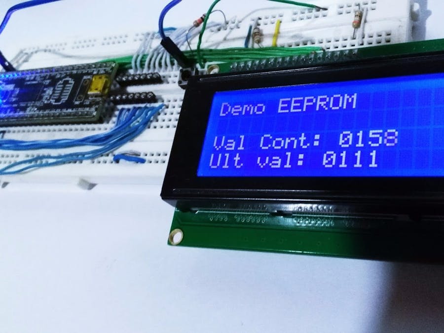
Project that we will build is a simple 4 digit counter, we will use a pulse generated by a PWM along with the use of an interruption it will increase the counter digit by digit, it is done this way because as stated above we will compare each digit with the ASCII table and save the characters in each position of the EEPROM memory, therefore we will use four memory locations to store our 4-digit counter.
Once you remove power to our counter, the last count value will be saved in the memory, so when you re-energize, the counter restarts from the value where it has been previously, thanks to the reading of this value stored in the EEPROM memory.
The General Target will be to learn to Read and Write data within EEPROM memory
Once we are sure on how to handle data writing/reading,we will be able to do more complex data operations and of any type in general. Remember our recommendation on using a ASCII table.
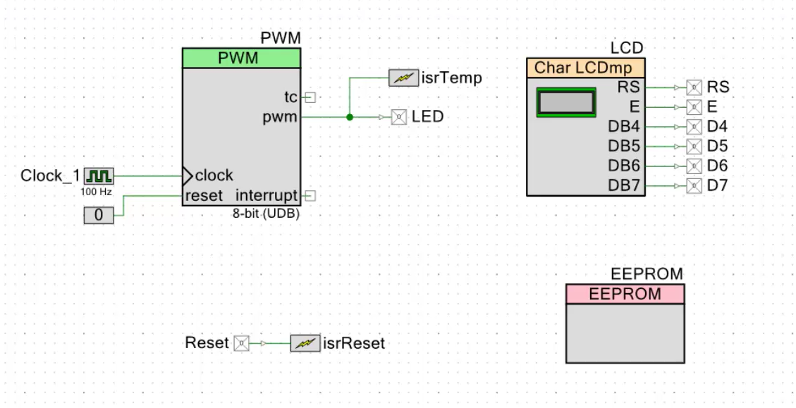
HardwareThe first thing to say is that the PWM has a clock very slow, therefore we need a few counts for 1 sec, which has LED attached to its output to indicate us that it's actually running at 1 sec, also has an interruption linked which provide us the increase, one to one, of the digits.
We need to show the data, for this we will use the LCD Custom component, where we can assign the pins to where we want, each output pin of the LCD Custom is assigned to a strong drive pin and is assigned with names so as not to get confused. This component can be downloaded at the end of the article and will have to be added manually.
We also need the EEPROM memory block, no need to configure anything, everything for this EEPROM memory block is all done by software, it will be enough then to include the EEPROM memory block to the schematic diagram.
Finally we add a reset button, it is external only to show that also it also works, the pin must be configured as input pull-up resistive and leads to an interruption on rising edge. This reset will simply write zeros in the EEPROM memory and restart the program to start at count 0.
What to do before you compile this program:
There is a work around the compiler so sprintf can operate correctly:
- We will access the compiler options and there we have to add the - u option printf float as shown in the figure:
- After this we have to go to system tab under pin configuration and we must change the heap size from 0x80 to 0x200.
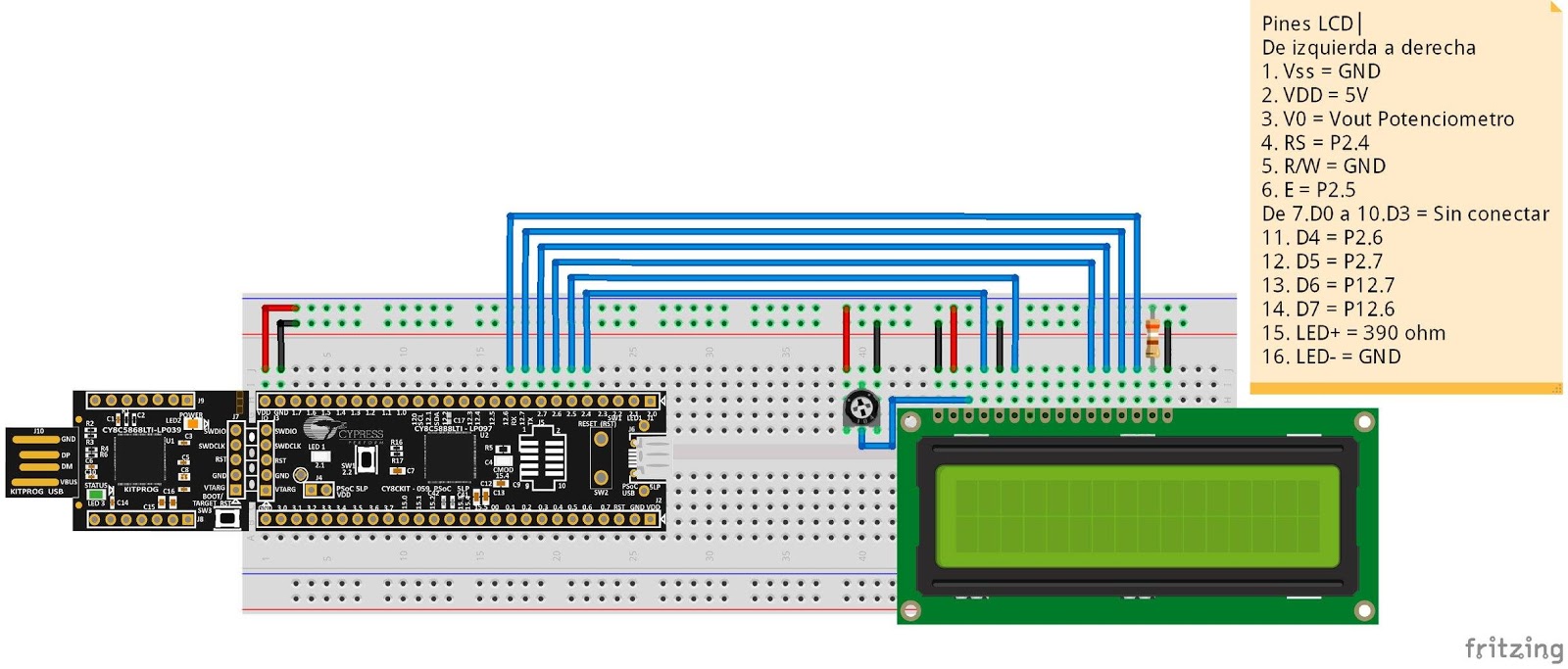
Now we have to put everything on the protoboard and wire it up, quit simple because we only have to wire the LCD so it can show the whole process. The LCD we are using is wired al it looks here:
And the only thing needed to be wired on the protoboard is the external button with a pull-down resistor used for reseting, as shown in the following image:
The only thing that changed here is the use of a 10K resistor instead of the 4K7 resisor.
SoftwareAs it had already been explained, it is a project that is based more on software then hardware, so will give the complete description of the algorithm and leave the software well commented so you can understand what the code is doing:
The first thing done was to start from the interruption generated by the PWM, in the method used for interrups, increase rules are made, split up the 4 digits of the counter and assign them to a 4 position vector. Each time an interruption is generated the rules of increase digits are followed, thus completing the 4 digit counter, from 0 to 9999. Following this, in the same method of interruption, it makes the conversion of the vectors of integers to vectors of characters (ASCII), necessary to be able to store in the EEPROM memory, what follows is writing in the EEPROM memory using the following statement:
writeStatus=EEPROM_WriteByte(numaimp[3],0);
The writeStatus variable refers to whether reading or writing was correct, the EEPROM_WriteByte () function returns a 0 or 1 refers to whether the writing was correct, so in this way we can have a good process control.
This instruction receives two parameters, the first one is the data to written, in this case will be a character of 8 bits to be stored. The second parameter refers to the address, or direction, as said at the beginning it's in a binary form but you could write the equivalent in interger format. For this project we will use the memory addresses 0, 1, 2 and 3.
The code takes care of storing the 4 digits
In the method of initialization is added the lines that are used for reading the EEPROM memory which are:
read[i]=EEPROM_ReadByte(i);
It is a simple instruction, receives the address which we want to read and returns us the data on it, in this case we will do it through a for cycle, ask for addresses from 0 to 3 and save these in a vector of characters called reading.
But this vector reading would not be useful because we cannot make operations with it, therefore we changed character to an integer.
Therefore this last vector whole will be which can operate, and it assigned to the first vector numbers so that it could continue the increases from where it was going.
Finally what remains to be done is to add the functionality of the reset. Simply it is necessary to add the method of the interruption tied to the reset button, this only through the function to write data to the EEPROM memory, we write zeros in the memory positions that we are using so the process could be resumed, apply a reset thru software, which is:
CySoftwareReset();
This is roughly the outline of the algorithm used for this project, we will leave the complete code commented here:
#include <project.h>
#include <stdio.h>//library to use the function sprintf
#include <stdlib.h>//library to use the function atoi and itoa
#include <string.h>//library for handling characters
int numero[4]={0,0,0,0};//vector of 4 positions where each digit of the counter will be
char numaimp[4];//vector containing the 4 digits but converted into character for storage in EEPROM
char lectura[4];// vector that stores the characters read from the memory EEPROM
cystatus writeStatus;//Variable to check if writing was successful or not
int i=0;//variable used in the for cycle reading
CY_ISR(InterruptReset)
{
   for(i=0;i<=3;i++)// for cycle writing zeros in the EEPROM
   {
       writeStatus=EEPROM_WriteByte('0',i); // writing in the memory addresses that are using the zeros
   }
   if(writeStatus == CYRET_SUCCESS)
   {
   }else{
   }
   CySoftwareReset();// reset por software
}
CY_ISR(InterruptTemp)// Interrupcion linked to the PWM that is generated every 1 sec.
{
   /*********************************************************************
   You have to understand the logic of a 4 digit counter,
   to use one to one we must ask for each digit, once you arrive to 10,
   increase the next digit and return to zero the previous,
   once that is increased the digit more significant to 10,
   mean that we have overflowed the counter then you must return all the variables to zeros
   *********************************************************************/
   numero[3]=numero[3]+1;
   if(numero[3]==10)
   {
       numero[2]=numero[2]+1;
       numero[3]=0;
   }
   if(numero[2]==10)
   {
       numero[1]=numero[1]+1;
       numero[2]=0;
       numero[3]=0;
   }
   if(numero[1]==10)
   {
       numero[0]=numero[0]+1;
       numero[1]=0;
       numero[2]=0;
       numero[3]=0;
   }
   if(numero[0]==10)
   {
       numero[0]=0;
       numero[1]=0;
       numero[2]=0;
       numero[3]=0;
   }
   /*
   This function sprintf converts all vector integers to character in the numaimp variable for storage
   */
   sprintf(numaimp,"%d%d%d%d",numero[3],numero[2],numero[1],numero[0]);
   writeStatus=EEPROM_WriteByte(numaimp[0],3);//Data storage for the variable numaimp in the memory address 3
   writeStatus=EEPROM_WriteByte(numaimp[1],2);//Data storage for the variable numaimp in the memory address 2
   writeStatus=EEPROM_WriteByte(numaimp[2],1);//Data storage for the variable numaimp in the memory address 1
   writeStatus=EEPROM_WriteByte(numaimp[3],0);//Data storage for the variable numaimp in the memory address 0
}
int main()
{
   CyGlobalIntEnable;
   PWM_Start();//PWM initialization
   EEPROM_Start();//EEPROM initialization
   LCD_Start();//LCD initialization
   LCD_Position(0,0);//position 0,0
   LCD_PrintString("Demo EEPROM");//print text
   isrTemp_StartEx(InterruptTemp);//it links the interruption of the pwm in the schematic one, with the method executes
   isrReset_StartEx(InterruptReset);// the interruption of the reset linked in the schematic with the method that executes
   for(i=0;i<=3;i++)//for cycle dedicated to read EEPROM memory and save the data in the vector read
   {
       lectura[i]=EEPROM_ReadByte(i);//Lectura de eeprom, recibe la dirección y devuelve el dato de dicha direccion
   }
   numero[0]=(int)(read[0]-48);// conversion of the variable read from the EEPROM that is character to entire
   numero[1]=(int)(read[1]-48);// conversion of the variable read from the EEPROM that is character to entire
   numero[2]=(int)(read[2]-48);// conversion of the variable read from the EEPROM that is character to entire
   numero[3]=(int)(read[3]-48);// conversion of the variable read from the EEPROM that is character to entire
   for(;;)
   {
       LCD_Position(2,0);//position 2,0 LCD
       LCD_PrintString("Val Cont: ");// print text
       LCD_PutChar(numaimp[3]);//Print variable converted to character of the integer that is increasing
       LCD_PutChar(numaimp[2]);
       LCD_PutChar(numaimp[1]);
       LCD_PutChar(numaimp[0]);
       LCD_Position(3,0);// position 3,0 LCD
       LCD_PrintString("Ult val: "); // print text
       LCD_PrintString(read);// Prints the variable read that makes reference to the number that was saved in the EEPROM
   }
}
Only assign the pins to LCD, LED and the reset button and do performance testing, the images of the final project running:
Finally sharing a video of this project, explained everything in detail (SPANISH):
Please do not forget to share.
PSoCLatinoamérica Team.


Comments