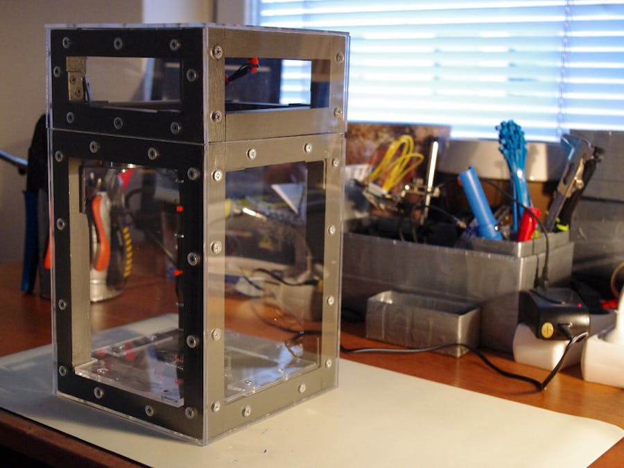
I have built a box with an electro magnetic lock controlled by a rfid-reader. The purpose of the project was to build a box that would work for rfid chips implanted in the hand. But since I haven’t an implanted chip yet I haven’t been able to test this. So for now you need a card or some other kind of rfid-tag.
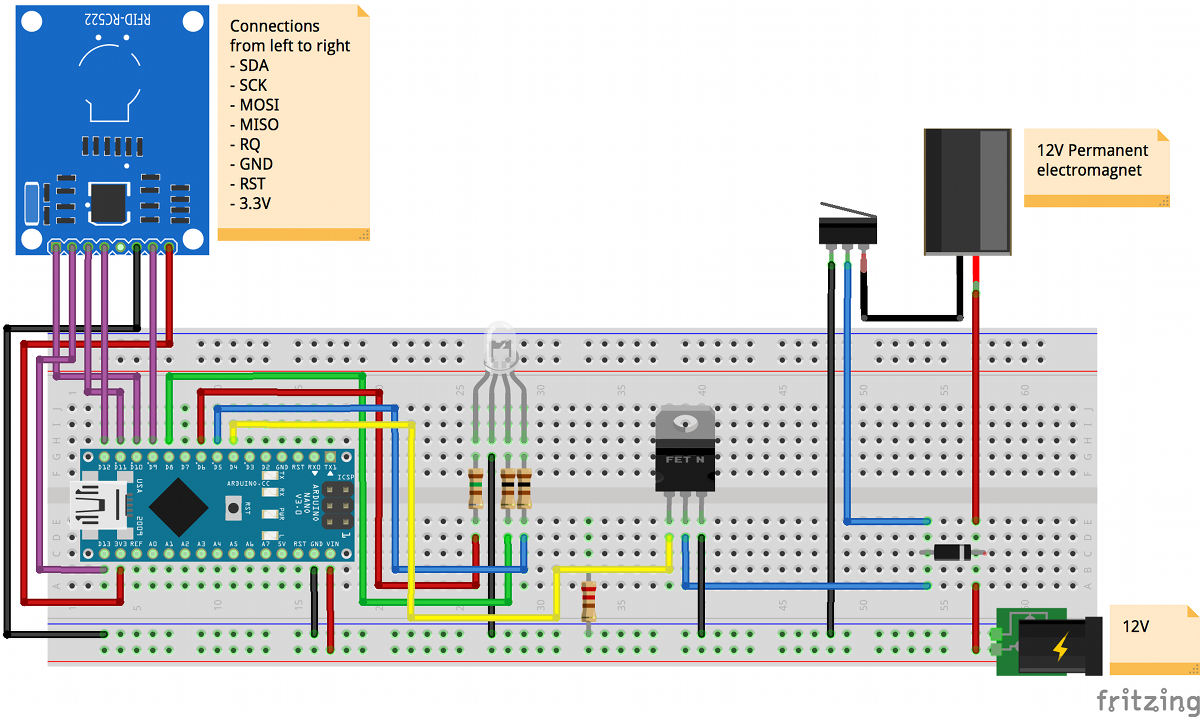
The hardwareI started out with Arduino Yun but quite quickly a replaced the Yun with the smaller Arduino Nano. Beside the Ardoino Nano I have used the a permanent 12V electromagnet, a rfid-reader, N-channel MOSFET, a diode, a micro switch and a RGB led.
There are a couple of reasons for selecting a permanent electromagnet instead of a normal electromagnet. With a permanent magnet you don't have to supply power to the magnet when the box is idle (closed) which of course makes it consume less power and the box also appears “locked” even when the power if disconnected. Another reason is that the magnet becomes very warm when the power is on. I started out with a magnet with the pulling power of 45N but after my initial tests I realised that I would need a stronger magnet. In the finished box I used a 300N magnet which works great.
The mosfet is used to control the power supply for the 12v electromagnet and the microswitch is used to make sure that the current to the magnet is on whenever the lock is open. I added the switch to make sure that the magnet wouldn’t make the lid slam down on my fingers but after testing I’m not sure it’s needed.
I had never used a mosfet and it’s been a long time since I used any kind of transistor. After googling for similar projects I found a good blog post that described the mosfet and how to use it.
To get some kind of user interface I added a RGB led and different actions results in different signals from the led. Green = A valid tag is present, Red = an invalid tag is present, White = The add tag was used and Blue for the delete tag.
Finally I mounted and soldered all the electronics on a small board and the board was then mounted in the bottom of the box between two sheets of plexiglass.
The box itself is built of wood and plexiglass. I have used 21 mm square wood strips for the structure and then covered everything with 3mm acrylic sheets. More about my experiences with plexiglass can be found beneath.
The software is quite straght forward. I’m listening to the rfid-reader and whenever a valid tag is present I supply current to the mosfet allowing the current to flow from the power supply to the magnet. The code also supports adding and removing valid tags.
The I have used the MFRC522 library for communicating with the rfid-reader and EepromUtil for storing tags when they are added. All code can be found on GitHub and the project contains four main parts:
- The ino-file with the main loop and and the handling of the led
- The RfidReader-class which is built as a factory returning an instance of the reader. In this case it was the RC522-reader. Note: that the implementation for the other reader (RDM630) does not work yet.
- The RfidTagHandler-class that’s handling the valid tag list and everything that has to do with adding, deleating and saving tags. Note: that the Add-tag and Deleate-tag is hardcoded and has to be changed if you are using this code.
- The RfidTag-class which is a small object for the tag itself
- The first thing I did was to get the electronic to work on a breadboard. I have added a schematics file describing how its setup. The biggest challenge for me was to get the mosfet to work as intended, but this blog post helpt me. The blog post also describes why it's a good idea to add the diode.
- When everything worked as intended I soldered everything on a smaller board as shown on the pictures above.
- When I’ve finished the work with the electronics I started to build the box. My first thought was to build id with aluminum profiles but after some thought I decided to use wood instead. The frame is built of 21 mm wood strips and to get the fram as straight as possible I used miter saw.
- When the frame was finished (but not painted) I mounted the magnet and the metal brick that together with the magnet creates the locking mechanism. This was a bit tricky and after some failed attempts I decided to mount the magnet in the corner by cut away a small part of the frame. When the magnets were mounted I painted the frame grey.
- With the finished frame the next step was to mount the electronics and the plexiglass. I started with the bottom of the box where the Arduino-board is mounted. Here I got my first experience with cutting plexiglass. I started to use the special knife that worked well for straight cuts but it didn’t work very well for small adjustments, like cutting a space for the frame in the corner. For that a metal saw worked a lot better. Another learning was that plexiglass breaks quite easy if you’re not careful when screwing the sheets to the frame.
I’ll continue to work with rfid-readers and together with an implanted rfid-chip the goal is to find and tryout different ways to add a personalised layer to things. So, hopefully I will post more projects soon.
Thanks for reading!


Comments
Please log in or sign up to comment.