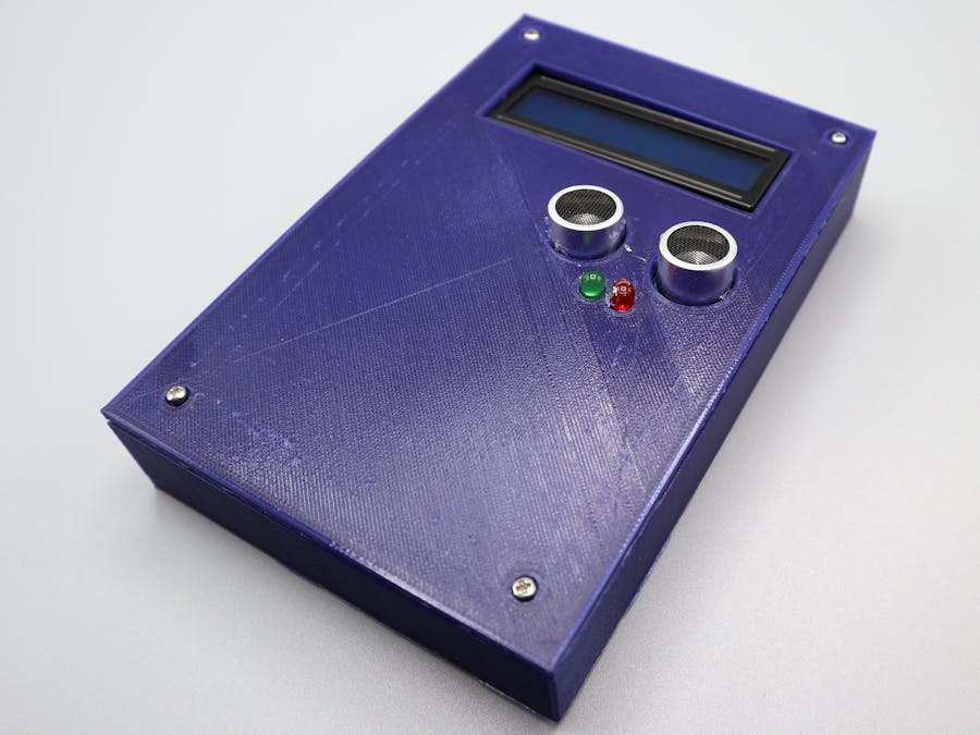
The Covid pandemic has made going to the gym a nightmare, because of this we decided to build a pushup counter to give us some workout motivation.
**Note: We use a 3D printed case in this project, the 3D files are available in the resources section below. If you do not have a 3D printer you can build your own case out of cardboard or some other material.**
To start we will need to remove the client from its blue case, rendering it a “naked” client. To do this remove the Phillips head screw from back of the case and the two internal Phillips heads screws that affix the client to the case.
Next, gather your LEDs and 4 jumper wires. Be sure to note which legs of the LEDs are short (GND) and long (positive).
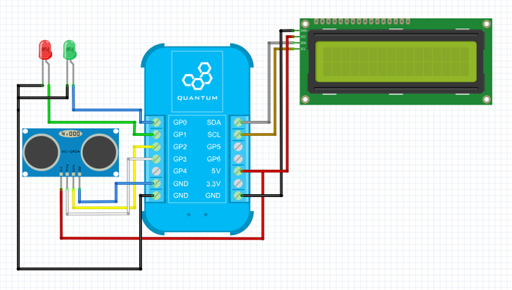
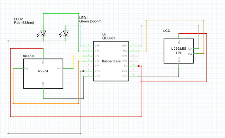
Wire your LEDs to the Builder Base as follows.
Next, gather your LCD and 4 more MF jumper wires. Connect the female ends of the wires to the 4 pins on the LCD and then connect the 4 male ends to the Builder Base as follows.
Now we will connect the distance sensor to the Builder Base. Start by again connecting 4 MF jumper wires to the four pins on the distance sensor and then connect the distance sensor to the Builder Base as follows.
Lastly we will wire our 5v power supply DIY Kit to the circuit. Take two MM jumper wires, connect them to the screw terminals on the power supply, and then connect them to the Builder Base as follows.
Now the circuit is complete. If you wired it correctly, the led on the Builder Base and the LCD should illuminate when you switch the power supply on!
**Before you proceed with this step you will want to download the 3D model and print it out. The Model is available in the resources section.**
Now we will place the Pushup Counter in its housing. Let’s start with the Client.
Place the client on the posts highlighted in the photo below and secure it with the two screws that held the client in its original case.
Now, place the LCD on the posts highlighted below and secure it with two M3 x 5mm bolts.
Now, place the 5v power supply on the post highlighted below and secure it with a M3x5mm bolt.
Now place the 9v batter in the slot highlighted below. This slot is designed to be a friction fit, so no additional hardware is needed to secure it to the case.
Now we will attach the LEDs and the Distance sensor to the front of the case. Because neither the LEDs nor the distance sensor have mounting holes, we simply hot glued them to the lid of the case.
Lastly, we will secure the top with 2 M2 screws.
Congrats, your pushup counter project is now complete!
Step 3: Build the FirmwareUsing the toolbar on the left hand side, navigate to the firmware builder. Select “+ Create New” on the upper left hand side of the screen.
Next, name your firmware file “Pushup Counter” and hit “Create”.
Now, select the “+ Add Device” button. You can find a device by using the search bar, or by scrolling through the list. Find and select, the “LED” device, name it Green, and click “Add Device”.Now do this a second time, but name the second LED RED.Let’s configure the LEDS.
For the green LED, from the driver drop-down menu select “GPIO”. For the Pin select GP0, and for the mode select Initially Low.
For the Red LED select GPIO for the driver, GP1 for the pin, and initially low for the mode.
Next we will add the LCD and HC-sr04 distance sensor to the firmware file.
Let’s configure the LCD. Select the Generic LCD2004 Display (I2C), set the I2C Address to 0x27 and the layout to 2x16.
**The I2C address may differ for your LCD, so be sure to check the documentation for the specific LCD that you have.**
Lastly, we will configure the distance sensor. Select the HC-SR04 driver from the driver dropdown menu. Set the Echo Pin to GP2, the Trigger Pin to GP3, and leave the Resolution unchanged.
**You can change the units from metric to imperial in Server’s settings.**
The firmware file is now complete! Save and upload it to the client you have the pushup counter attached to!
**Make sure that your Q-Server Application is up to date! We are constantly improving our system and updating our object library, because of this some newer versions of code objects might not work on older systems.**
Navigate from the Firmware Builder to the App Builder via the toolbar on the left side of the screen.
Once there, click “+ Create New”.
Name your app and hit create.
You will be redirected to the canvas where you will build your App.
Using the search bar on the left hand side of the canvas, find and drag the following hardware objects onto the canvas in the designated quantities.
Arrange them as shown.
Click on each of the hardware objects and name them via the properties panel on the right hand side of the screen. We named the distance sensor “distance sensor”, the LCD “LCD”, and the LEDs “Red” and “Green”.
**Be sure to save the properties for each Hardware object using the save button on the properties panel. If you do not save the properties after you deselect the hardware objects your changes will be lost.**
Now, drag two value compare and two digital toggle code objects onto the canvas and connect them as shown.
We named one of the number compare objects Top and the other Bottom. We did this because they will be used to check wether the user has gone to the top or the bottom of the pushup stroke.
Select the “Number 1” port on the “Top” Code object by clicking on the port, and toggle the “Trigger” switch to ON through the Properties Panel. Be sure to save the properties after you’ve made this change.
Now, repeat the steps above for the “Number 1” port on the “Bottom” code object.
Next we will configure “Number 2” ports for both the “Top” and “Bottom” code objects. With the “Number 2” “Top” port selected use the Properties Panel for the “Top” code object to set the “Number 2” port on the object to 35 and leave the trigger switch in the OFF position. Now, for the “Bottom” object set the “Number 2” port on the object to 5 and, again, leave the “Trigger” switch in the OFF position.
**Be sure to save the properties after changing the configurations for these ports, if you don’t your changes will be lost and you will have to redo them!**
**Our sever is set to metric units, so if you have yours set to imperial units you will want to change convert values to be reflected in inches!**
5cm=2in
35cm=14in
This block of code takes in the distance value given from the distance sensor and passes it to both the “Top” and the “Bottom” number compare objects through both of their “Number 1” ports. Because the “Number 1” ports are set to trigger, the Number Compare function is triggered and the value of the “Number 1” port is compared against the value set in the “Number 2” port. In the case of the “Top” compare object if the distance is greater than or equal to 35cm, a trigger signal will be sent to the “Toggle Up” toggle object.
The same is true for the “Bottom” compare object, but it will only trigger if the distance value is less than or equal to 5cm, and the trigger signal from it will be sent to the “Toggle Down” toggle object.
We will now add a Digital AND code object to the canvas. Place it and connect it to the Digital Toggle objects as shown below.
Now, configure the “In 1” port on the Digital AND object through its properties panel. Set the trigger switch to the ON position.
The Digital AND object ensures that the full pushup has been completed as it will only trigger if both the Up and the Down positions have been achieved. We set only the “In 1” port to trigger, because we want the pushup to be counted as complete when the person doing the pushup goes down and the up.
We will now connect the “Out” port on the AND object to “Reset” port on both of the digital toggle objects.
Once the AND block is triggered (pushup is completed) we have it reset the Toggle objects so that another pushup can be done and recorded.
We will now add a Timeout and another Digital Toggle code object onto the canvas. Arrange them as shown.
The “Out” port from the AND object is connected to both the “In” port on the Timeout object and the “Toggle” port on the Digital Toggle object.
Now configure the “Delay (ms)” port on the Timeout object to 700.
Connect the “Out” port to the Green LED, and the “Out Inverted” port to the red LED hardware objects.
When one pushup is completed the AND object Triggers the Timeout and Toggle objects simultaneously. The Toggle object is normally set to have the the Red LED on and the Green LED off. So, when the Digital toggle object is triggered the states of the LEDs switch. While this state switch occurs, the 700ms timeout executes and once complete resets the Toggle object so that the Green LED is off and the Red LED is on.
We will now add a Data Counter and a Static Number code object onto the canvas. Arrange them as shown.
Now, connect the AND object to the Data Counter and Static Number objects as shown.
Set the “Value” port on the Static Number object to 14. Be sure to save the changes you made to the to Static Number Property Panel!
Now, connect the “Value” out port from the Data Counter to the “Send to Display” and the “String” ports on the LCD.
Next, connect the “Value” out port from the Static Number object to the “Column Position” port on the LCD.
Now, add an Initial Trigger and a Static String code object to the canvas. Arrange them as shown.
Next, we will set the “String” port on the Static String object to “Pushup Count:”
Now, connect the “Trigger” out port to the “Trigger” in port on the Static String object.
Next, connect the “Trigger” out port from the Initial Trigger object to the “Clear” port on the LCD.
Lastly, we will connect the “String” port to both the “String” and “Send to Display” ports on the LCD.
Here’s a brief high level description of what is going on in the application.
When the application is started the Initial Trigger clears the LCD and triggers the Static String object which sends the string “Pushup Count:” to the LCD to be displayed.
Meanwhile, the the Distance Sensor sends data to the “Top” and “Bottom” Number Compare blocks. If the comparison criteria is met, the compare blocks then trigger the Toggle Up/Down objects which in turn trigger the AND block. However, the AND block will only evaluate to true and send out a trigger signal if the “Toggle Up” triggers the and block after the “Toggle Down” block has triggered. Once the AND block triggers, the Red LED is toggled OFF and the Green LED is toggled ON for 700ms and then the states are reversed.
The AND block also increments the count of the pushups, and sends that number to be displayed on the LCD. The reason why the Column Position is set to 14 is so that the number of pushups will be displayed on the LCD after the “Pushup Count:” string.
That’s it! Save your application. We are now ready to Map the application and do some pushups!
Step 5: Map the HardwareYou should now be back on the Apps page.
Find your “Pushup Counter” app and hit the play button.
A list containing all of the devices in your application will expand.
Next click on the “LCD” device and the client dropdown menu will appear on the right.
Select the LCD driver from the dropdown menu and hit “Done”.
Repeat the same steps for the remaining Drivers.
Notice how the status symbols have changed to green checkmarks.
**When mapping firmware devices to objects in your Apps it is important to note that only devices and objects of the same type can be mapped together.**
Step 6: Run the Application!Congrats on building your first project, It’s now time to use it!
Hit “Save + Run”.
Voila! Your Pushup Counter is now complete.


_SSo5XmN3eS.jpg?auto=compress%2Cformat&w=48&h=48&fit=fill&bg=ffffff)


Comments
Please log in or sign up to comment.