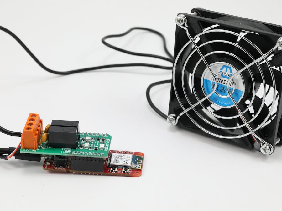
This demo was created for Microchip's booth at Google Next 2019. Attendees in San Francisco used a simple Google Cloud interface to control a lamp located at a residence in Phoenix (over 700 miles away).
We like this demo not just because it terrified my roommates, but also because it is very simple.
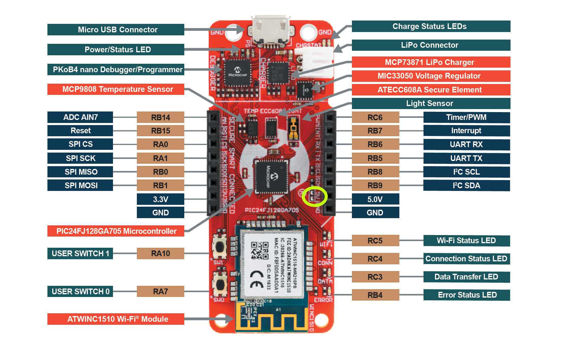
The PIC-IoT WG board is pre-configured to securely connect to Google Cloud Platform out of the box. Upon startup, you're directed to a sandbox account, which contains a simple interface with controls for you to learn about the capabilities of your board.
So if you have a PIC-IoT WG board, Relay Click, and a USB-powered device that you're willing to sacrifice, you can expect to have a cloud-connected gadget in around an hour.
Before You StartFollow the Quick Start Guide to configure your Wi-Fi connection and start streaming temperature and light data.
Setup your development environment and get started on building a sensor node foundation. We will build off of this pre-configuration to customize the design.
Note: This demo requires 5V supply to the relay board and draws a fair amount of current (up to 100mA). For this reason it is not suitable as a battery operated sensor and requires the permanent connection to the USB power supply.
Safety ReminderAlways use caution when working with relays. Do not touch the relay while the power supply is on, and avoid applying high voltage to the click. The click is to be used by trained personnel when applying high voltage. Please read all relevant information on the Relay Click product page.
This tutorial is intended for use with direct current (DC) applications only. We recommend USB-powered lamps, fans, disco balls, etc.
What You Will LearnIn this tutorial, you will learn how to add cloud controls to a simple actuator through the PIC-IoT WG board. You will do this by connecting an expansion board (the click board) and providing the necessary logic to interpret commands received from the Cloud via the config channel (MQTT subscription to the device unique “config” topic).
Solder the 5V BridgeBecause the Relay Click draws 5V, you will need to solder the bridge located next to the 5V pin of the mikroBUS header.
We connected the bridge with a zero-ohm resistor.
Connect the Mikroe Relay ClickSimply plug the Click into the MikroBUS socket.
Program the MCU1. Connect the board to your PC and follow the steps described in the sensor node foundation tutorial to create a new project in MPLAB X.
2. Open your MCC config file if you have closed it
3. In Device Resources (bottom left) and scroll to the list to expand the Mikro E-Clicks folder
4. Select Relay under Miscellaneous and double-click to add it to the project
5. The Easy Setup dialog window will open and expose the Information tab.
6. Select the Configuration tab and ensure that the Generate Example option is selected.
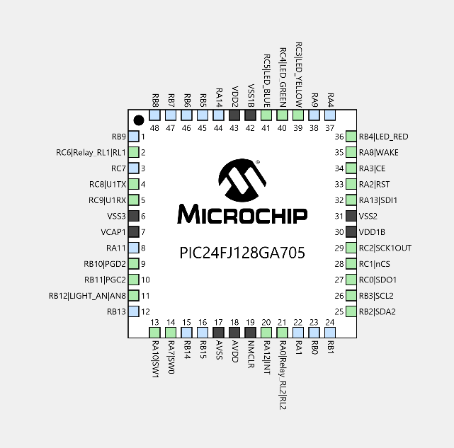
7. Navigate to the Pin Manager - Grid View, and assign the I/O pins to the Relay control lines according to the PIC-IoT WG board pinout as follows:
8. Click the Generate button in the Resource Management window (top left) to add the generated header files to your project
9. Navigate back to your project files and verify that four new files have been added to the basic sensor foundation project skeleton: Relay_app.c and Relay_example.c (and corresponding.h files)
10. Open the Relay_app.h file and note the new functions created
11. Open the main.c file and locate the receivedFromCloud() function:
12. Edit the code as follows:
void receivedFromCloud(uint8_t *topic, uint8_t *payload)
{
    char *rl1Token = "\"RL1\":";
    char *rl2Token = "\"RL2\":";
    char *subString;
    if ((subString = strstr((char*)payload, rl1Token)))
    {
        if ( subString[strlen(rl1Token)] == '1' ) RELAY_RL1_Engage();
        else RELAY_RL1_Disengage();
    }
    if ((subString = strstr((char*)payload, rl2Token)))
    {
        if ( subString[strlen(rl2Token)] == '1' ) RELAY_RL2_Engage();
        else RELAY_RL2_Disengage();
    }
    // debug_printer(SEVERITY_NONE, LEVEL_NORMAL, "topic: %s", topic);
    debug_printer(SEVERITY_NONE, LEVEL_NORMAL, "payload: %s", payload);
}
13. CleanandBuild the project by pressing the hammer icon in the toolbar
14. Make and Program the board using the green arrow button on the toolbar.
15. Navigate back to the CURIOSITY drive
16. Open CLICK-ME.htm to open the uniquely configured Google Cloud Portal.
17. Scroll to the ControlYour Device section and create two new toggle controls, RL1 and RL2
18. Activate any of the two toggle controls and press the Send to Device button, after a second or less, the corresponding Relay will activate with a loud click. A corresponding LED on the Relay Click will also activate (red for Relay 1, yellow for Relay 2).
Build Your Application19. Disconnect everything from power
20. Cut and strip the wires on the lamp.
21. Connect the wires to the relay and clamp them down well. Make sure that each relay contains the same wire andthat none of the copper wires touch.
22. Use the Micro-USB cable to connect the PIC-IoT WG to a power supply. Also connect the lamp to power.
23. Back in the Google Cloud portal, turn both RL1 and RL2 on and click Send to Device.
24. Copy the unique URL that is generated when you clicked on CLICK-ME.htm and access it from anywhere to control the lamp. As the sandbox does not store data, you will need to add the RL1 and RL2 toggle each time you refresh the page.
What did you build? Comment below to let us know!


_BKghDQOwE2.png)


Comments
Please log in or sign up to comment.