IntroductionI set out to build a robotic arm capable of moving cups from position A to B as part of a larger goal to automate dishwashing. This project also gave me an opportunity to explore and apply mechanical engineering skills, complementing my background in programming. The following outlines the steps I’ve taken and the progress I’ve made so far.
CAD DesignEach joint of the arm is controlled by a cycloidal drive. I spent to bulk of this project design & manufacturing the cycloidal drive. I chose this gear system for the robot arm since it product a high torque (in this case, a 1:20 gear reduction ratio), minimal backlash, fairly small size & assembly, and also it was a gear system I wanted to try making for myself. Everything was designed in Autodesk Fusion. All design files are linked at the bottom of the article as "Fusion CAD files".
Each cycloidal drive is controlled by a Nema 17 stepper at the input shaft.
It drives the output shaft with a 1:20 gear reduction ratio.
Here are some clips showing how the cycloidal drive works.
This is a clip of the cycloidal drive assembled. Parts were made with 3D printing services from PCBWay.
This is how it can be assembled to form an arm.
This is a design showing how the cycloidal drives are used to form the base, shoulder, and elbow joints.
This is a clip showing the shoulder joint assembled.
For the end effector, I was planning on making a differential drive with a gripper attached to it. This is the progress I had made on it so far. Essentially, two Nema 17s would control a bevel gear box, and when the 2 motors rotated in the same direction the end effector would rotate up or down. And when they moved in opposite directions, the end effect would stay still by rotating the wrist in place.
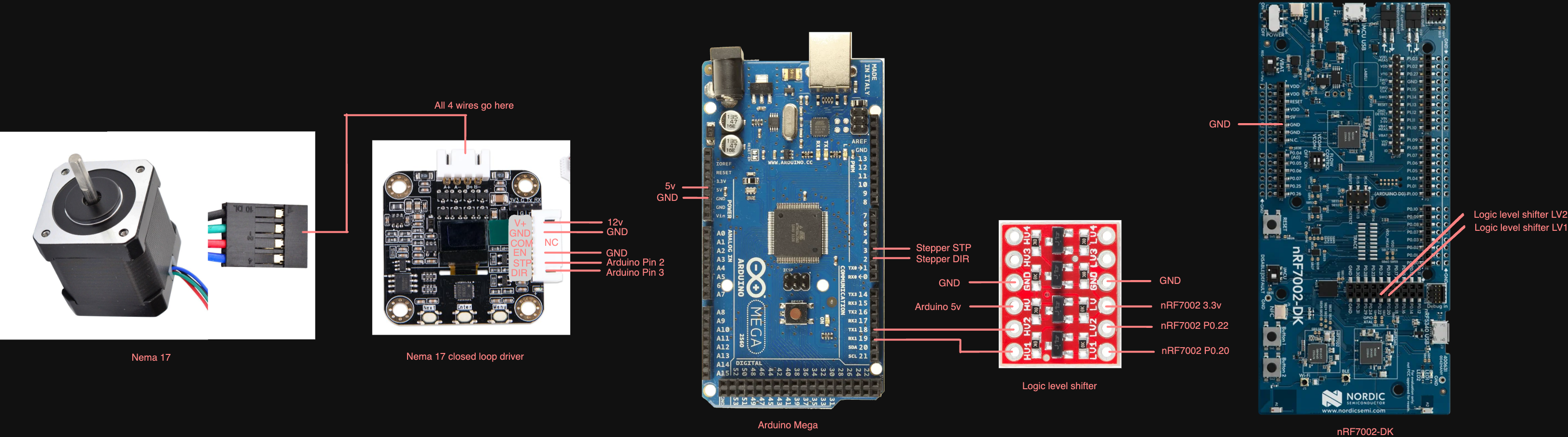
ElectronicsEach Nema 17 motor is controlled by a Nema 17 closed loop stepper motor driver. The driver is controlled by an Arduino Mega to tell it what angle to go to. The nRF7002-DK controls the Arduino Mega over UART. A logic level shifter is used between the 2 boards since the Arduino operates at 5v whereas the nRF board operates at 3.3v.
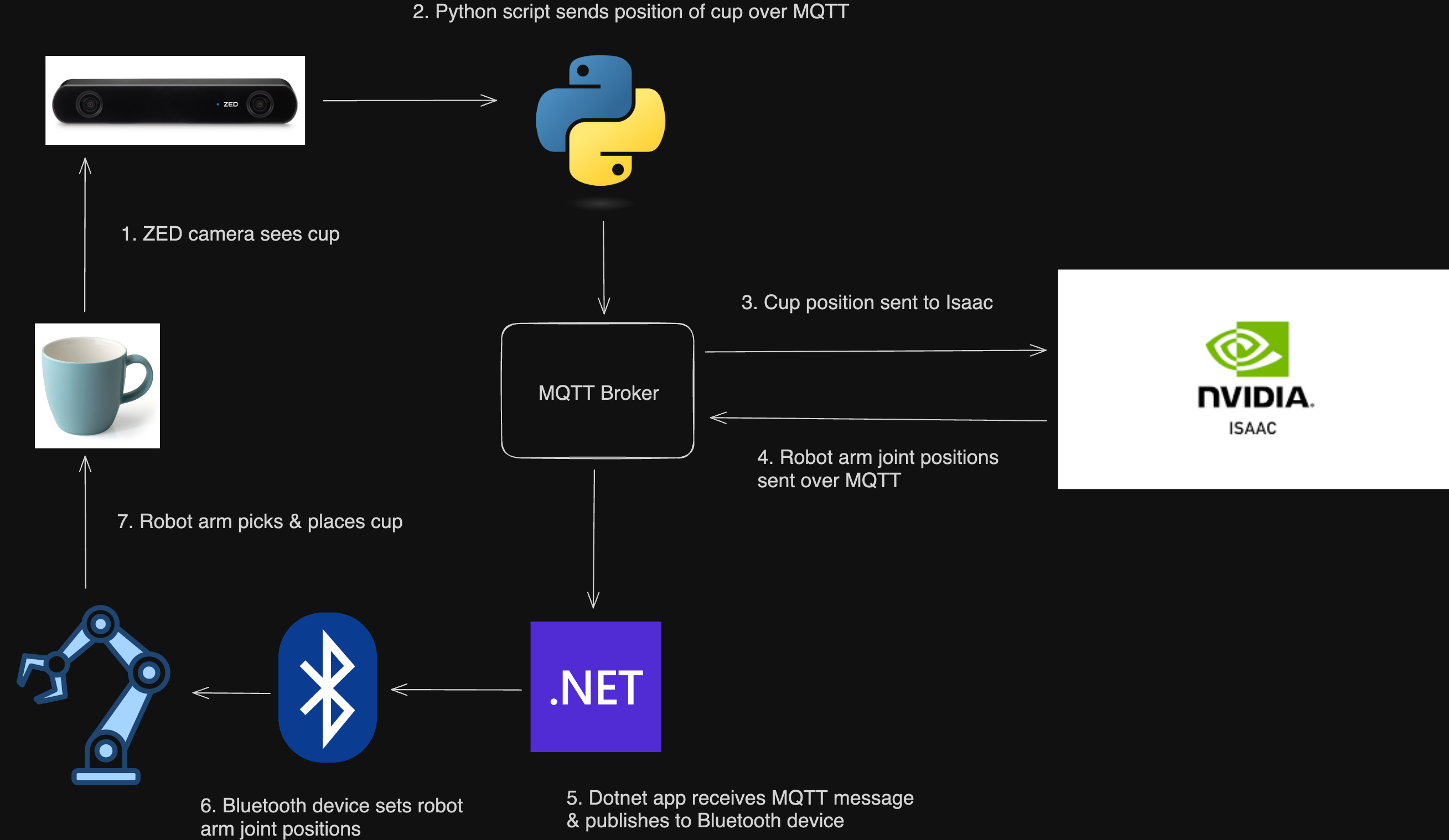
SoftwareThe system operates as follows. All the code is linked in the GitHub repo at the bottom of the article.
Arduino Mega specifics (folder in repo is ArduinoMegaMotorController)
- It receives commands to set the target joint angles over UART1 to the nRF7002-DK & controls the stepper motors using the AccelStepper library
- It also reports the current joint angles back over UART1
nRF7002 specifics (folder in repo is nrf7002DKBluetoothPeripheral)
- It exposes a single Bluetooth service to set/get the angles of all robot joints, as well as the gripper open/close state which the Dotnet app will read/write to
- When a Bluetooth command is received to set the joint states, it sends the command over UART to the Arduino
- I use the default UART0 pin configuration (i.e., no board overlay override file), which you can see in the device tree configuration
MQTT broker (folder in repo is Dotnet/TestMQTTBroker)
- This spins up a local MQTT broker for all clients to subscribe/publish to
Dotnet web app specifics (folder in repo is Dotnet/BluetoothWebApp)
- It is a Blazor app that manually connects to the Bluetooth device & sends/receives data to the exposed Bluetooth service on the nRF7002-DK
- Any commands sent/received over Bluetooth are forwarded to the MQTT broker. The Nvidia Isaac app will receive/send commands to this Dotnet app.
- This is a demo video showing a connection to the nRF7002-DK over Bluetooth and messages being sent/received & forwarded to the MQTT broker. In the video, the Dotnet app connects to the nRF7002 over Bluetooth first. Then the physical buttons on the nRF7002 are pressed to increment/decrement all joint angle states, which is reflected in the web app. At the end, I show the MQTT communication between the web app and the MQTT broker, using Postman as a test client to subscribe/publish MQTT messages (in place of Nvidai Isaac).
Zed camera Python app specifics (folder in repo is Dotnet/ZedConsoleApp)
- Using the ZED sdk, it identifies the object & send the coordinates relative to the ZED camera over MQTT and will be received by the Nvidia Isaac app
- This video shows how the MQTT messages are sent from the Zed camera and update an object's position in Nvidia Isaac
Nvidia Isaac specifics (folder in repo is robot)
- It uses Cortex as a decider network (i.e. if cup is not picked up & is nearby, move arm to position x, y)
- It acts like a digital twin in which it represents the real world positions of the robot arm & cup
- It subscribes to the MQTT broker to receive the cup position & the current robot joint angles
- It publishes to the MQTT broker to send the target robot joint angles
- This video shows how the Isaac app interacts sends/receives MQTT messages. The Postman client shows receiving of all joint states & also sending the real world position of an object (which would get sent by the Zed Python app)
ConclusionThe project was a great opportunity to delve into all aspects of robotics (mechanical, software, electrical) and put it into application. Although the project is still in the works, I thought I'd share the progress I've made on it so far. So I hope you enjoy. Cheers!

_wBlXbAhKpM.gif?auto=format%2Ccompress&gifq=35&w=400&h=300&fit=min)


_wzec989qrF.jpg?auto=compress%2Cformat&w=48&h=48&fit=fill&bg=ffffff)


_t9PF3orMPd.png?auto=compress%2Cformat&w=40&h=40&fit=fillmax&bg=fff&dpr=2)


Comments